Kia Niro: Dual Clutch Transmission Control System / Inhibitor Switch Repair procedures
| Inspection |
Inspect the following items by referring to inspection flow chart. (Refer to Inhibitor Switch - "Troubleshooting") |
| 1. |
Check the diagnostic trouble codes (DTC) using KDS/GDS. |
| 2. |
Inspect if "N" range setting matches. (Refer to Inhibitor Switch - "Installation") |
| 3. |
Check the free play for shift cable. (Refer to Shift Cable - "Installation") |
| 4. |
Check the condition of connector.
|
| 5. |
Inspect ground condition of rear combination lamp circuit. |
| 6. |
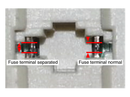
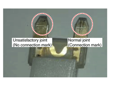
Inspect wiring connection condition of junction box power terminal and fuse lamp.
|
| 7. |
Check the inhibitor switch circuit signal.
Signal Code Table
|
| Removal |
|
| 1. |
Place the shift lever in the "N" position. |
| 2. |
Shut off the high voltage circuit. (Refer to Automatic Transaxle System - "High Voltage Shut-off Procedure") |
| 3. |
Drain the coolant of hybrid cooling system. (Refer to Hybrid Motor System - "Coolant") |
| 4. |
Remove the hybrid power control unit (HPCU) assembly. (Refer to Hybrid Control System - "Hybrid Power Control Unit") |
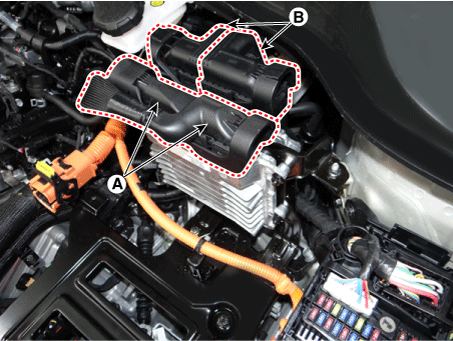
| 5. |
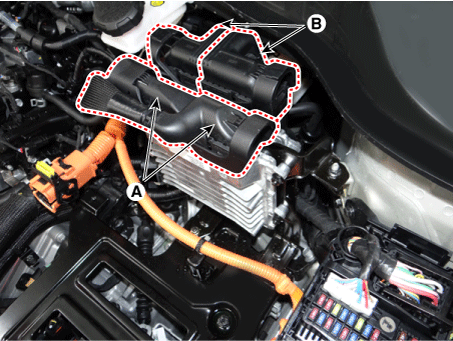
Disconnect the TCM connector (A) and ECM connector (B).
|
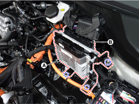
| 6. |
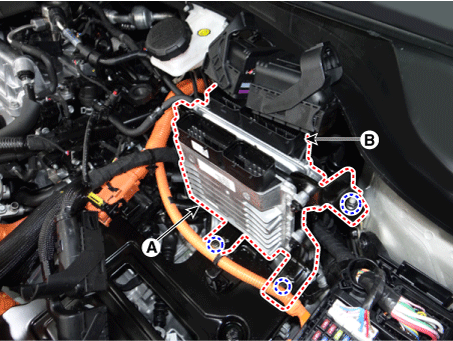
Remove the TCM (A) and ECM (B).
|
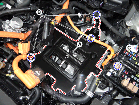
| 7. |
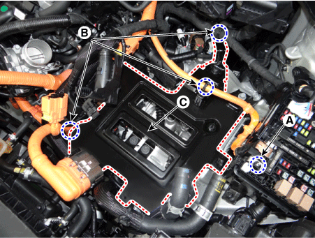
Remove the HPCU tray (C) after removing the nut (A) and wiring mounting clips (B).
|
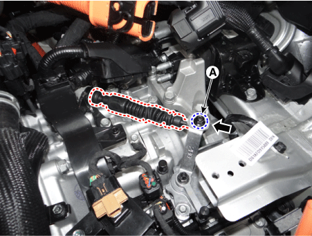
| 8. |
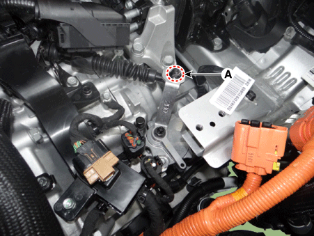
Loosen the shift cable mounting nut (A).
|
| 9. |
Remove the manual control lever (A).
|
| 10. |
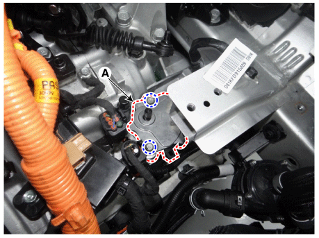
Remove the inhibitor switch (A).
|
| Installation |
| 1. |
Check that the shift lever is placed in the "N" position. |
| 2. |
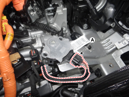
Conntect the inhibitor switch connector (A).
|
| 3. |
Install the inhibitor switch (A).
|
| 4. |
Install the manual control lever (A).
|
| 5. |
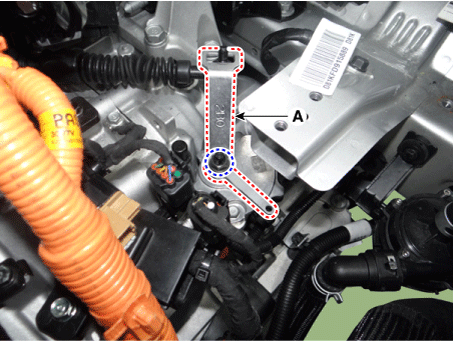
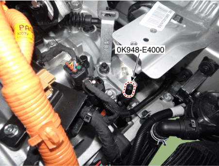
Align the hole in the manual control lever with the "N" position hole of the inhibitor switch and then insert the SST inhibitor switch guide pin (0K948-E4000).
|
| 6. |
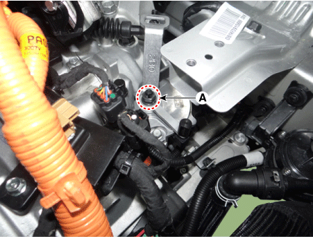
Tighten the manual lever mounting nut (A) to the specified torque.
|
| 7. |
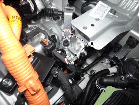
Tighten the inhibitor switch mounting bolts (B) to the specified torque.
|
| 8. |
Tighten the nut (A) to the specified torque after removing free play by pushing the shift cable in the direction of the arrow.
|
| 9. |
Remove the SST (0K948-E4000) from the adjusment hole. |
| 10. |
Install the HPCU tray (A).
|
| 11. |
Install the wiring mounting clips (B) to HPCU tray and the tighten the nut (C).
|
| 12. |
Install the TCM (A) and ECM (B).
|
| 13. |
Connect the TCM connector (A) and ECM (B) connector.
|
| 14. |
Install the hybrid power control unit (HPCU) assembly. (Refer to Hybrid Control System - "Hybrid Power Control Unit" |
| 15. |
Refill the hybrid motor cooling system with coolant. (Refer to Hybrid Motor System - "Coolant") |
| 16. |
Connect the high voltage circuit. (Refer to Automatic Transaxle System - "High Voltage Shut-off Procedure") |
 Inhibitor Switch Troubleshooting
Troubleshooting
...
 Shift Lever Components and components location
Components
1. Shift lever knob & boots
2. Shift lever assembly
3. Shift cable assembly
...
Other information:
Kia Niro 2017 (DE HEV) Service Manual: Center Pillar Trim Components and components location
Component Location
1. Center pillar lower trim
2. Center pillar upper trim
...
Kia Niro 2017 (DE HEV) Service Manual: Audio Unit Repair procedures
Removal
•
When removing with a flat-tip screwdriver or remover, wrap protective
tape around the tools to prevent damage to components.
•
When ...


