Kia Niro: Hybrid Control System / Hybrid Control Unit (HCU) Schematic diagrams
| HCU Terminal And Input/Output Signal |

| Terminal Function |
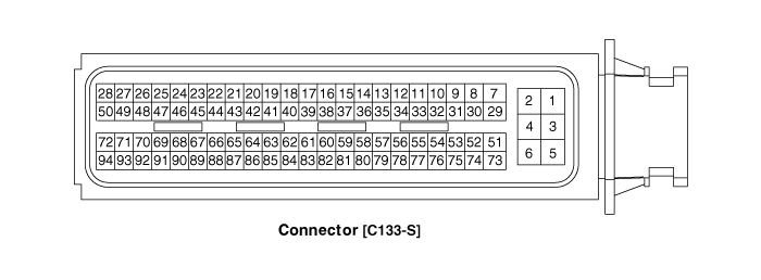
Connector [C133-S]
|
Pin No. |
Description |
Connected to |
|
1 |
HCU ground |
Chassis ground |
|
2 |
HCU ground |
Chassis ground |
|
3 |
HCU ground |
Chassis ground |
|
4 |
Battery power (B+) |
Battery |
|
5 |
Battery power (B+) |
Battery |
|
6 |
Battery power (B+) |
Battery |
|
7 |
- |
|
|
8 |
- |
|
|
9 |
- |
|
|
10 |
- |
|
|
11 |
- |
|
|
12 |
- |
|
|
13 |
- |
|
|
14 |
- |
|
|
15 |
Brake Switch 2 signal input |
Brake Switch (NC, IG1) |
|
16 |
Brake Switch 1 signal input |
Brake Switch (NO, B+) |
|
17 |
- |
|
|
18 |
- |
|
|
19 |
- |
|
|
20 |
- |
|
|
21 |
- |
|
|
22 |
- |
|
|
23 |
- |
|
|
24 |
- |
|
|
25 |
- |
|
|
26 |
- |
|
|
27 |
- |
|
|
28 |
- |
|
|
29 |
- |
|
|
30 |
- |
|
|
31 |
- |
|
|
32 |
- |
|
|
33 |
- |
|
|
34 |
- |
|
|
35 |
- |
|
|
36 |
- |
|
|
37 |
- |
|
|
38 |
Start signal input |
Inhibitor Switch |
|
39 |
- |
|
|
40 |
- |
|
|
41 |
- |
|
|
42 |
- |
|
|
43 |
- |
|
|
44 |
- |
|
|
45 |
- |
|
|
46 |
- |
|
|
47 |
- |
|
|
48 |
- |
|
|
49 |
- |
|
|
50 |
- |
|
|
51 |
- |
|
|
52 |
- |
|
|
53 |
- |
|
|
54 |
- |
|
|
55 |
- |
|
|
56 |
- |
|
|
57 |
- |
|
|
58 |
- |
|
|
59 |
- |
|
|
60 |
- |
|
|
61 |
- |
|
|
62 |
- |
|
|
63 |
- |
|
|
64 |
- |
|
|
65 |
- |
|
|
66 |
- |
|
|
67 |
- |
|
|
68 |
- |
|
|
69 |
- |
|
|
70 |
- |
|
|
71 |
- |
|
|
72 |
- |
|
|
73 |
IGN signal input |
Smart Key Unit |
|
74 |
- |
|
|
75 |
L - CAN [High] |
Engine clutch Actuator |
|
76 |
L - CAN [Low] |
Engine clutch Actuator |
|
77 |
- |
|
|
78 |
Powertrain CAN [High] |
Other control modules |
|
79 |
Powertrain CAN [Low] |
Other control modules |
|
80 |
- |
|
|
81 |
Hybrid CAN [High] |
Other control modules |
|
82 |
Hybrid CAN [Low] |
Other control modules |
|
83 |
- |
|
|
84 |
- |
|
|
85 |
- |
|
|
86 |
- |
|
|
87 |
- |
|
|
88 |
- |
|
|
89 |
- |
|
|
90 |
- |
|
|
91 |
- |
|
|
92 |
- |
|
|
93 |
- |
|
|
94 |
- |
|
| Input/Output signal |
Connector [C133-S]
|
Pin no. |
Description |
Condition |
Type |
Level |
|
1 |
HCU ground |
Always |
DC Voltage |
Max. 50mV |
|
2 |
HCU ground |
Always |
DC Voltage |
Max. 50mV |
|
3 |
HCU ground |
Always |
DC Voltage |
Max. 50mV |
|
4 |
Battery power (B+) |
Always |
DC Voltage |
Battery Voltage |
|
5 |
Battery power (B+) |
Always |
DC Voltage |
Battery Voltage |
|
6 |
Battery power (B+) |
Always |
DC Voltage |
Battery Voltage |
|
7 |
- |
|
|
|
|
8 |
- |
|
|
|
|
9 |
- |
|
|
|
|
10 |
- |
|
|
|
|
11 |
- |
|
|
|
|
12 |
- |
|
|
|
|
13 |
- |
|
|
|
|
14 |
- |
|
|
|
|
15 |
Brake Switch 2 signal input |
IG ON |
DC Voltage |
Battery Voltage |
|
16 |
Brake Switch 1 signal input |
Always |
DC Voltage |
Battery Voltage |
|
17 |
- |
|
|
|
|
18 |
- |
|
|
|
|
19 |
- |
|
|
|
|
20 |
- |
|
|
|
|
21 |
- |
|
|
|
|
22 |
- |
|
|
|
|
23 |
- |
|
|
|
|
24 |
- |
|
|
|
|
25 |
- |
|
|
|
|
26 |
- |
|
|
|
|
27 |
- |
|
|
|
|
28 |
- |
|
|
|
|
29 |
- |
|
|
|
|
30 |
- |
|
|
|
|
31 |
Sensor power (+5V) |
IG ON |
DC Voltage |
4.9 - 5.1V |
|
32 |
Sensor ground |
IG ON |
DC Voltage |
Max. 50mV |
|
33 |
Clutch Pressure Sensor (CPS) signal input |
IG ON |
Analog |
0.5 - 4.5V |
|
34 |
- |
|
|
|
|
35 |
- |
|
|
|
|
36 |
- |
|
|
|
|
37 |
- |
|
|
|
|
38 |
Start signal input |
IG ST |
DC Voltage |
Battery Voltage |
|
39 |
- |
|
|
|
|
40 |
- |
|
|
|
|
41 |
- |
|
|
|
|
42 |
- |
|
|
|
|
43 |
- |
|
|
|
|
44 |
- |
|
|
|
|
45 |
- |
|
|
|
|
46 |
- |
|
|
|
|
47 |
- |
|
|
|
|
48 |
- |
|
|
|
|
49 |
- |
|
|
|
|
50 |
- |
|
|
|
|
51 |
- |
|
|
|
|
52 |
- |
|
|
|
|
53 |
- |
|
|
|
|
54 |
- |
|
|
|
|
55 |
- |
|
|
|
|
56 |
- |
|
|
|
|
57 |
- |
|
|
|
|
58 |
- |
|
|
|
|
59 |
- |
|
|
|
|
60 |
- |
|
|
|
|
61 |
- |
|
|
|
|
62 |
- |
|
|
|
|
63 |
- |
|
|
|
|
64 |
- |
|
|
|
|
65 |
- |
|
|
|
|
66 |
- |
|
|
|
|
67 |
- |
|
|
|
|
68 |
- |
|
|
|
|
69 |
- |
|
|
|
|
70 |
- |
|
|
|
|
71 |
- |
|
|
|
|
72 |
- |
|
|
|
|
73 |
IGN signal input |
IG ON |
DC Voltage |
Battery Voltage |
|
74 |
- |
|
|
|
|
75 |
L - CAN [High] |
IG ON |
Pulse |
|
|
76 |
L - CAN [Low] |
IG ON |
Pulse |
|
|
77 |
- |
|
|
|
|
78 |
Powertrain CAN [High] |
IG ON |
Pulse |
Dominant:2.75 - 4.5(3.5)V Receive:2.0 - 3.0(2.5)V |
|
79 |
Powertrain CAN [Low] |
IG ON |
Pulse |
Receive:2.0 - 3.0(2.5)V Dominant:0.5 - 2.25(1.5)V |
|
80 |
- |
|
|
|
|
81 |
Hybrid CAN [High] |
IG ON |
Pulse |
Dominant:2.75 - 4.5(3.5)V Receive:2.0 - 3.0(2.5)V |
|
82 |
Hybrid CAN [Low] |
IG ON |
Pulse |
Receive:2.0 - 3.0(2.5)V Dominant:0.5 - 2.25(1.5)V |
|
83 |
- |
|
|
|
|
84 |
- |
|
|
|
|
85 |
- |
|
|
|
|
86 |
- |
|
|
|
|
87 |
- |
|
|
|
|
88 |
- |
|
|
|
|
89 |
- |
|
|
|
|
90 |
- |
|
|
|
|
91 |
- |
|
|
|
|
92 |
- |
|
|
|
|
93 |
- |
|
|
|
|
94 |
- |
|
|
|
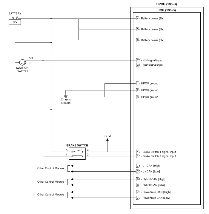
| Circuit Diagram |

 Hybrid Power Control Unit (HPCU) Repair procedures
Removal
•
Be sure to read and follow the “General Safety Information and
Caution” ...
 Hybrid Control Unit (HCU) Repair procedures
Removal
•
Be sure to read and follow the “General Safety Information and
Caution” ...
Other information:
Kia Niro (DE HEV) Owners Manual: Installing a Child Restraint System (CRS)
WARNING
Before installing your Child Restraint System always:
Read and follow the instructions provided by the manufacturer of the Child
Restraint System.
Failure to follow all warnings and instructions could increase the risk of
the SERIOUS INJURY or DEATH if an accident occurs.
WARNING
If ...
Kia Niro 2017 (DE HEV) Service Manual: Brake Line Repair procedures
Removal
1.
Disconnect the brake fluid level switch connector, and remove the reservoir
cap.
2.
Remove the brake fluid from the master cylinder reservoir with a syringe.
...
