Kia Niro: Cooling System / Cooling Fan Repair procedures
| Removal and Installation |
Cooling Fan Assembly
| 1. |
Disconnect the negative battery terminal. |
| 2. |
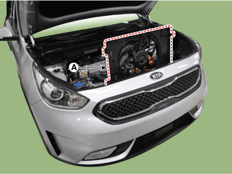
Remove the air cleaner and air duct A. (Refer to Intake and Exhaust System - "Air Cleaner") |
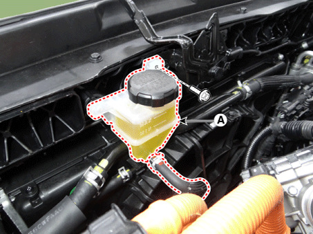
| 3. |
Separate the engine clutch reservoir tank (A).
|
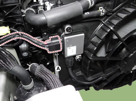
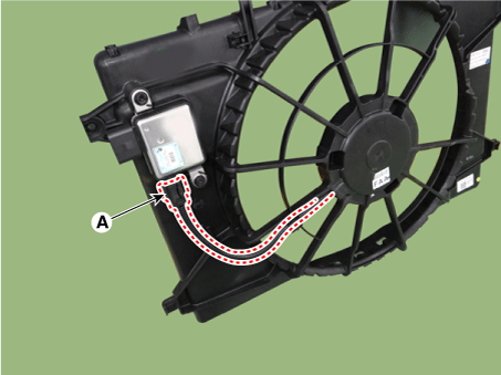
| 4. |
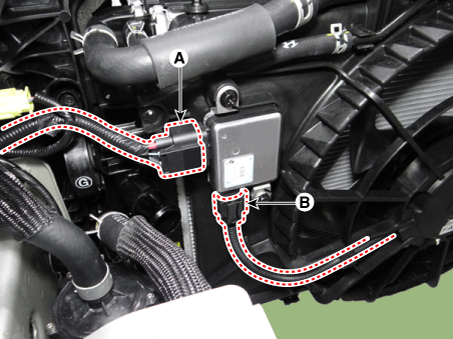
Disconnect the cooling fan control module (PWM) connector (A).
|
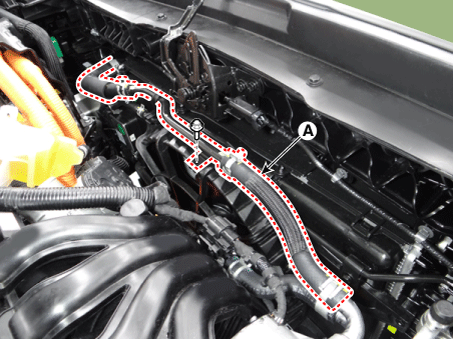
| 5. |
Remove the hybrid starter generator coolant hose & pipe (A) from the cooling fan shroud.
|
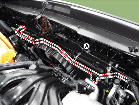
| 6. |
Separate the radiator coolant pipe (A) from the cooling fan shroud.
|
| 7. |
Remove the air dam (A).
|
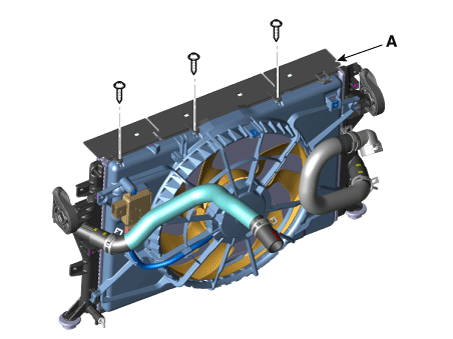
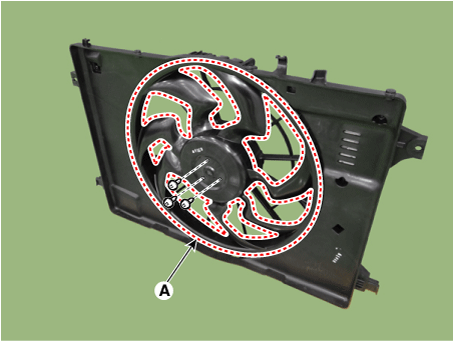
| 8. |
Remove the cooling fan assembly (A).
|
| 9. |
Install in the reverse order of removal. |
Cooling Fan Control Module (PWM)
| 1. |
Disconnect the battery negative terminal. |
| 2. |
Remove the air duct. (Refer to Intake and Exhaust System - "Air Cleaner") |
| 3. |
Disconnect the cooling fan control module (PWM) connector (A) and cooling fan motor connector (B).
|
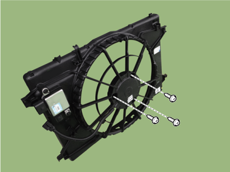
| 4. |
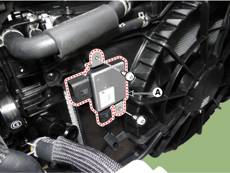
Remove the cooling fan control module (PWM) (A).
|
| 5. |
Install in the reverse order of removal. |
| Disassembly |
| 1. |
Remove the cooling fan (A) from cooling fan shroud.
|
| 2. |
Disconnect the cooling fan motor connector (A).
|
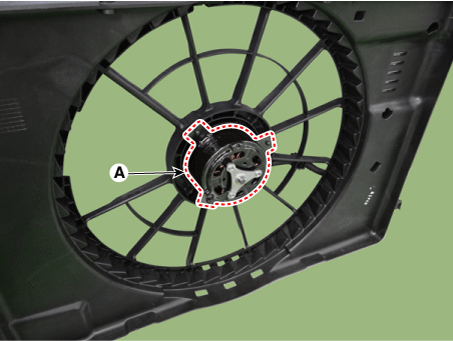
| 3. |
Remove the cooling fan motor (A) from cooling fan shroud.
|
| 4. |
Install in the reverse order of removal. |
| Inspection |
Fan Motor
| 1. |
Disconnect the fan motor connector from the resistor. |
| 2. |
Connect the battery voltage to the "+" terminal and ground to " - " terminal. |
| 3. |
Check the cooling fan motor operates well. |
 Cooling Fan Schematic diagrams
Circuit Diagram
PWM Circuit Diagram
...
 Radiator Components and components location
Components
1. Reservoir tank
2. Radiator reservoir hose & pipe
3. Radiator
4. Radiator upper hose
5. Radiator lower hose
6. Radiator upper ...
Other information:
Kia Niro 2017 (DE HEV) Service Manual: Hybrid Power Control Unit (HPCU) Schematic diagrams
Hybrid Power Control Unit
(HPCU) connector and high voltage cable
Hybrid Power Control Unit
(HPCU) terminal And Input/Output signal
ECM Terminal Function
Connector [C133-S]
(94Pin) : HPCU signal input and control
Terminal
...
Kia Niro (DE HEV) Owners Manual: USB charger
The USB charger is designed to recharge batteries of small size electrical devices
using a USB cable.The electrical devices can be recharged when the Engine Start/Stop
button is in ACC/ON/START position.
The battery charging state may be monitored on the electrical device.
Disconnect the USB ...
