Kia Niro: Smart Key System / Smart Key Unit Repair procedures
| Removal |
Put on gloves to prevent hand injuries. |

|

Smart Key Unit
| 1. |
Disconnect the negative (-) battery terminal. |
| 2. |
Remove the glove box housing. (Refer to Body - "Glove Box Housing") |
| 3. |
Remove the body control module (BCM). (Refer to Body Electrical System - "Body Control Module (BCM)") |
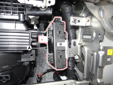
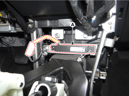
| 4. |
Remove the smart key unit (A) after loosening the mounting bolt.
|
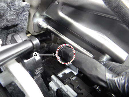
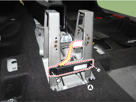
| 5. |
Remove the smart key unit wiring harness mounting clip (A).
|
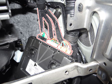
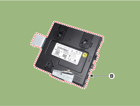
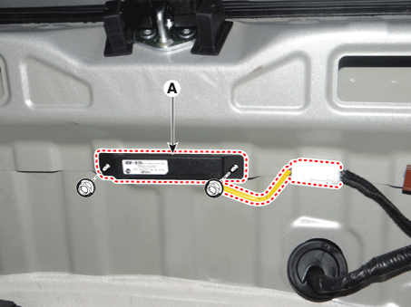
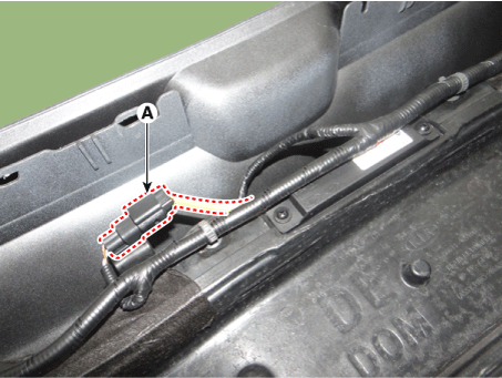
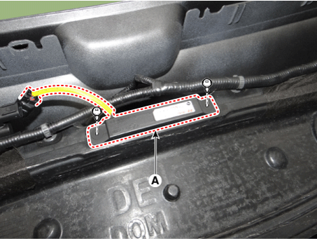
| 6. |
Remove the smart key unit (B) after disconnecting the connectors (A).
|
Interior 1 Antenna
| 1. |
Disconnect the negative (-) battery terminal. |
| 2. |
Remove the floor console assembly. (Reger to Body - "Floor Console Assembly") |
| 3. |
Remove the interior 1 antenna (A) after loosening the mounting bolt and nut and disconnecting the connector.
|
Interior 2 Antenna
| 1. |
Disconnect the negative (-) battery terminal. |
| 2. |
Remove the floor console assembly. (Reger to Body - "Floor Console Assembly") |
| 3. |
Remove the interior 2 antenna (A) after loosening the mounting screws and disconnecting the connector.
|
Tailgate Antenna
| 1. |
Disconnect the negative (-) battery terminal. |
| 2. |
Remove the rear transverse trim. (Reger to Body - " Rear Transverse Trim") |
| 3. |
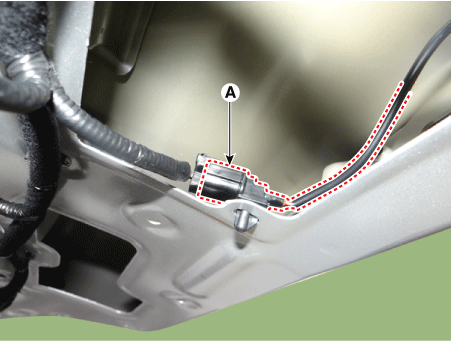
Remove the tailgate antenna (A) after loosening the mounting nuts and disconnecting the connector.
|
Rear Bumper Antenna
| 1. |
Disconnect the negative (-) battery terminal. |
| 2. |
Remove the rear bumper cover. (Refer to Body - "Rear Bumper Cover") |
| 3. |
Disconnect the rear bumper antenna connector (A).
|
| 4. |
Remove the rear bumper antenna (A) after loosening the mounting screws.
|
Buzzer
| 1. |
Disconnect the negative (-) battery terminal. |
| 2. |
Remove the front bumper cover. (Refer to Body - "Front Bumper Cover") |
| 3. |
Remove the left headlamp. (Refer to Lighting System - "Headlamps") |
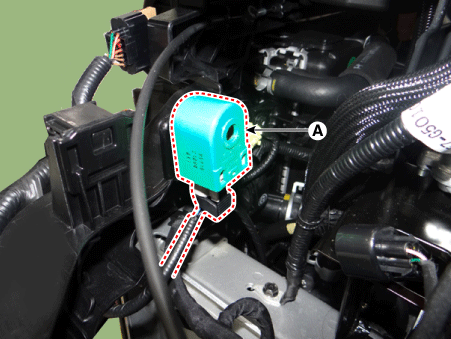
| 4. |
Remove the buzzer (A) after disconnecting the connector.
|
Door Outside Handle
| 1. |
Disconnect the negative (-) battery terminal. |
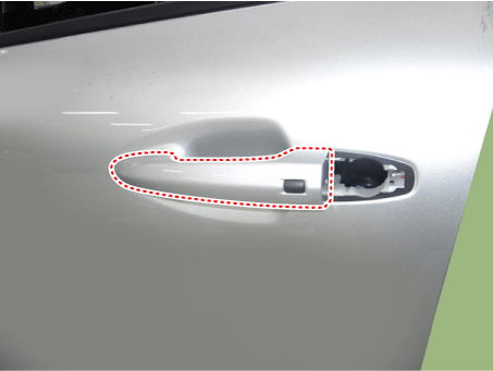
| 2. |
Remove the front door outside handle. (Refer to Body - "Front Door Outside Handle")
|
Tailgate Open Switch
| 1. |
Disconnect the negative (-) battery terminal. |
| 2. |
Remove the tailgate latch. (Refer to Body - "Tailgate Latch") |
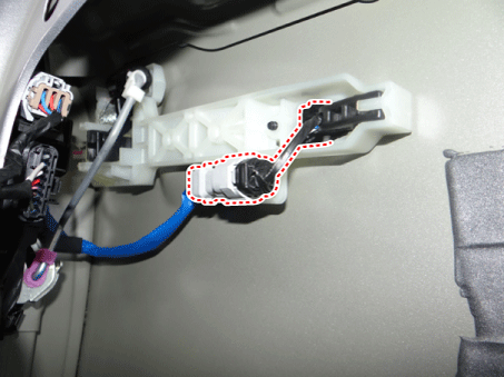
| 3. |
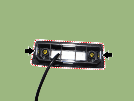
Disconnect the tailgate open switch connector (A).
|
| 4. |
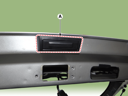
Remove the tailgate open switch assembly (A) after pushing mounting hooks.
|
| Inspection |
Smart Key Unit
(Refer to Smart Key System - "Smart Key Diagnostic")
Smart Key Switch
(Refer to Smart Key System - "Smart Key Diagnostic")
Antenna
(Refer to Smart Key System - "Smart Key Diagnostic")
Door Outside Handle
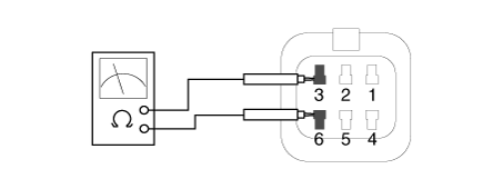
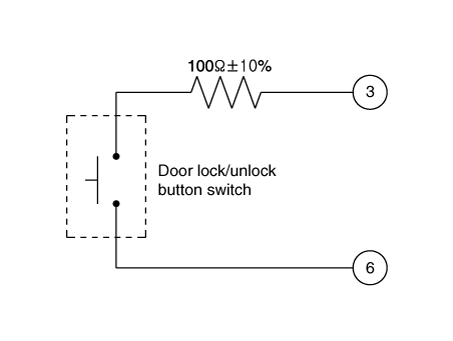
| 1. |
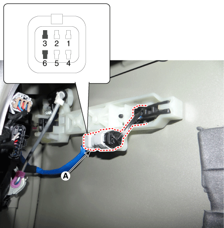
Disconnect the front door outside handle connector (A).
|
| 2. |
Check for continuity between terminals No 3 and No 6.
|
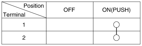
Tailgate Open Switch
| 1. |
Check for continuity between the tailgate open switch terminals.
|
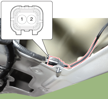
| 2. |
If continuity is not specified, inspect the switch
|
| Installation |
Smart Key Unit
| 1. |
Install the smart key unit after connecting the connectors. |
| 2. |
Install the smart key unit wiring harness mounting clip. |
| 3. |
Install the body control module (BCM). |
| 4. |
Install the glove box housing. |
| 5. |
Connect the negative (-) battery terminal and check the smart key system. |
Interior 1 Antenna
| 1. |
Install the interior 1 antenna. |
| 2. |
Install the floor console assembly. |
| 3. |
Connect the negative (-) battery terminal and check the smart key system. |
Interior 2 Antenna
| 1. |
Install the interior 2 antenna. |
| 2. |
Install the floor console assembly. |
| 3. |
Connect the negative (-) battery terminal and check the smart key system. |
Tailgate Antenna
| 1. |
Install the tailgate antenna. |
| 2. |
Install the rear transverse trim. |
| 3. |
Connect the negative (-) battery terminal and check the smart key system. |
Rear Bumper Antenna
| 1. |
Install the rear bumper antenna. |
| 2. |
Install the rear bumper cover. |
| 3. |
Connect the negative (-) battery terminal and check the smart key system. |
Buzzer
| 1. |
Install the buzzer. |
| 2. |
Install the left headlamp. |
| 3. |
Install the front bumper cover. |
| 4. |
Connect the negative (-) battery terminal and check the smart key system. |
Door Outside Handle
| 1. |
Install the front door outside handle. |
| 2. |
Connect the negative (-) battery terminal and check the smart key system. |
Tailgate Open Switch
| 1. |
Install the tailgate open switch assembly. |
| 2. |
Install the tailgate latch. |
| 3. |
Connect the negative (-) battery terminal and check the smart key system. |
 Smart Key Unit Schematic diagrams
Circuit Diagram
...
 Smart Key Diagnostic Repair procedures
Inspection
Self Diagnosis With
Scan Tool
It will be able to diagnose defects of SMART KEY system with KDS/GDS quickly.
KDS/GDS can operates actuator forcefully, input/output value mo ...
Other information:
Kia Niro 2017 (DE HEV) Service Manual: Repair procedures
General Inspection
Before and after servicing the EPS system, perform the troubleshooting and
test procedure as follows.
Compare the system condition with normal condition in the table below and
if abnormal symptom is detected, perform necessary remedy and inspe ...
Kia Niro 2017 (DE HEV) Service Manual: Front Door Module Repair procedures
Replacement
Put on gloves to protect your hands.
•
Use a plastic panel removal tool to remove interior trim pie ...
