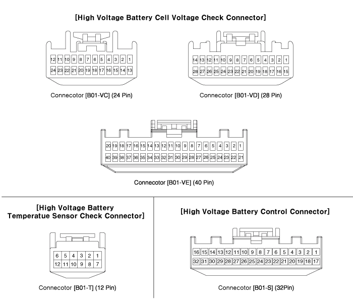
Pin No.
|
Description
|
Connected to
|
1
|
-
|
-
|
2
|
-
|
-
|
3
|
-
|
-
|
4
|
Battery Voltage [Module 1/ Cell 0] signal input
|
Battery Module [1]
|
5
|
Battery Voltage [Module 1/ Cell 2] signal input
|
Battery Module [1]
|
6
|
Battery Voltage [Module 1/ Cell 4] signal input
|
Battery Module [1]
|
7
|
Battery Voltage [Module 1/ Cell 6] signal input
|
Battery Module [1]
|
8
|
Battery Voltage [Module 1/ Cell 8] signal input
|
Battery Module [1]
|
9
|
Battery Voltage [Module 2/ Cell 1] signal input
|
Battery Module [1]
|
10
|
Battery Voltage [Module 2/ Cell 3] signal input
|
Battery Module [1]
|
11
|
Battery Voltage [Module 2/ Cell 5] signal input
|
Battery Module [1]
|
12
|
Battery Voltage [Module 2/ Cell 7] signal input
|
Battery Module [1]
|
13
|
-
|
-
|
14
|
-
|
-
|
15
|
-
|
-
|
16
|
Battery Voltage [Module 1/ Cell 1] signal input
|
Battery Module [1]
|
17
|
Battery Voltage [Module 1/ Cell 3] signal input
|
Battery Module [1]
|
18
|
Battery Voltage [Module 1/ Cell 5] signal input
|
Battery Module [1]
|
19
|
Battery Voltage [Module 1/ Cell 7] signal input
|
Battery Module [1]
|
20
|
Battery Voltage [Module 2/ Cell 0] signal input
|
Battery Module [1]
|
21
|
Battery Voltage [Module 2/ Cell 2] signal input
|
Battery Module [1]
|
22
|
Battery Voltage [Module 2/ Cell 4] signal input
|
Battery Module [1]
|
23
|
Battery Voltage [Module 2/ Cell 6] signal input
|
Battery Module [1]
|
24
|
Battery Voltage [Module 2/ Cell 8] signal input
|
Battery Module [1]
|
Pin No.
|
Description
|
Connected to
|
1
|
-
|
-
|
2
|
-
|
-
|
3
|
-
|
-
|
4
|
-
|
-
|
5
|
Battery Voltage [Module 3/ Cell 1] signal input
|
Battery Module [2]
|
6
|
Battery Voltage [Module 3/ Cell 3] signal input
|
Battery Module [2]
|
7
|
Battery Voltage [Module 3/ Cell 5] signal input
|
Battery Module [2]
|
8
|
Battery Voltage [Module 3/ Cell 7] signal input
|
Battery Module [2]
|
9
|
Battery Voltage [Module 4/ Cell 0] signal input
|
Battery Module [2]
|
10
|
Battery Voltage [Module 4/ Cell 2] signal input
|
Battery Module [2]
|
11
|
Battery Voltage [Module 4/ Cell 4] signal input
|
Battery Module [2]
|
12
|
Battery Voltage [Module 4/ Cell 6] signal input
|
Battery Module [2]
|
13
|
Battery Voltage [Module 4/ Cell 8] signal input
|
Battery Module [2]
|
14
|
-
|
-
|
15
|
-
|
-
|
16
|
-
|
-
|
17
|
-
|
-
|
18
|
Battery Voltage [Module 3/ Cell 0] signal input
|
Battery Module [2]
|
19
|
Battery Voltage [Module 3/ Cell 2] signal input
|
Battery Module [2]
|
20
|
Battery Voltage [Module 3/ Cell 4] signal input
|
Battery Module [2]
|
21
|
Battery Voltage [Module 3/ Cell 6] signal input
|
Battery Module [2]
|
22
|
Battery Voltage [Module 3/ Cell 8] signal input
|
Battery Module [2]
|
23
|
Battery Voltage [Module 4/ Cell 1] signal input
|
Battery Module [2]
|
24
|
Battery Voltage [Module 4/ Cell 3] signal input
|
Battery Module [2]
|
25
|
Battery Voltage [Module 4/ Cell 5] signal input
|
Battery Module [2]
|
26
|
Battery Voltage [Module 4/ Cell 7] signal input
|
Battery Module [2]
|
27
|
-
|
-
|
28
|
-
|
-
|
Pin No.
|
Description
|
Connected to
|
1
|
Battery Voltage [Module 5/ Cell 0] signal input
|
Battery Module [3]
|
2
|
Battery Voltage [Module 5/ Cell 2] signal input
|
Battery Module [3]
|
3
|
Battery Voltage [Module 5/ Cell 4] signal input
|
Battery Module [3]
|
4
|
Battery Voltage [Module 5/ Cell 6] signal input
|
Battery Module [3]
|
5
|
Battery Voltage [Module 5/ Cell 8] signal input
|
Battery Module [3]
|
6
|
Battery Voltage [Module 6/ Cell 1] signal input
|
Battery Module [3]
|
7
|
Battery Voltage [Module 6/ Cell 3] signal input
|
Battery Module [3]
|
8
|
Battery Voltage [Module 6/ Cell 5] signal input
|
Battery Module [3]
|
9
|
Battery Voltage [Module 6/ Cell 7] signal input
|
Battery Module [3]
|
10
|
Battery Voltage [Module 7/ Cell 0] signal input
|
Battery Module [4]
|
11
|
Battery Voltage [Module 7/ Cell 2] signal input
|
Battery Module [4]
|
12
|
Battery Voltage [Module 7/ Cell 4] signal input
|
Battery Module [4]
|
13
|
Battery Voltage [Module 7/ Cell 6] signal input
|
Battery Module [4]
|
14
|
Battery Voltage [Module 7/ Cell 8] signal input
|
Battery Module [4]
|
15
|
Battery Voltage [Module 8/ Cell 1] signal input
|
Battery Module [4]
|
16
|
Battery Voltage [Module 8/ Cell 3] signal input
|
Battery Module [4]
|
17
|
Battery Voltage [Module 8/ Cell 5] signal input
|
Battery Module [4]
|
18
|
Battery Voltage [Module 8/ Cell 7] signal input
|
Battery Module [4]
|
19
|
-
|
-
|
20
|
-
|
-
|
21
|
Battery Voltage [Module 5/ Cell 1] signal input
|
Battery Module [3]
|
22
|
Battery Voltage [Module 5/ Cell 3] signal input
|
Battery Module [3]
|
23
|
Battery Voltage [Module 5/ Cell 5] signal input
|
Battery Module [3]
|
24
|
Battery Voltage [Module 5/ Cell 7] signal input
|
Battery Module [3]
|
25
|
Battery Voltage [Module 6/ Cell 0] signal input
|
Battery Module [3]
|
26
|
Battery Voltage [Module 6/ Cell 2] signal input
|
Battery Module [3]
|
27
|
Battery Voltage [Module 6/ Cell 4] signal input
|
Battery Module [3]
|
28
|
Battery Voltage [Module 6/ Cell 6] signal input
|
Battery Module [3]
|
29
|
Battery Voltage [Module 6/ Cell 8] signal input
|
Battery Module [3]
|
30
|
Battery Voltage [Module 7/ Cell 1] signal input
|
Battery Module [4]
|
31
|
Battery Voltage [Module 7/ Cell 3] signal input
|
Battery Module [4]
|
32
|
Battery Voltage [Module 7/ Cell 5] signal input
|
Battery Module [4]
|
33
|
Battery Voltage [Module 7/ Cell 7] signal input
|
Battery Module [4]
|
34
|
Battery Voltage [Module 8/ Cell 0] signal input
|
Battery Module [4]
|
35
|
Battery Voltage [Module 8/ Cell 2] signal input
|
Battery Module [4]
|
36
|
Battery Voltage [Module 8/ Cell 4] signal input
|
Battery Module [4]
|
37
|
Battery Voltage [Module 8/ Cell 6] signal input
|
Battery Module [4]
|
38
|
Battery Voltage [Module 8/ Cell 8] signal input
|
Battery Module [4]
|
39
|
-
|
-
|
40
|
-
|
-
|
Pin No.
|
Description
|
Connected to
|
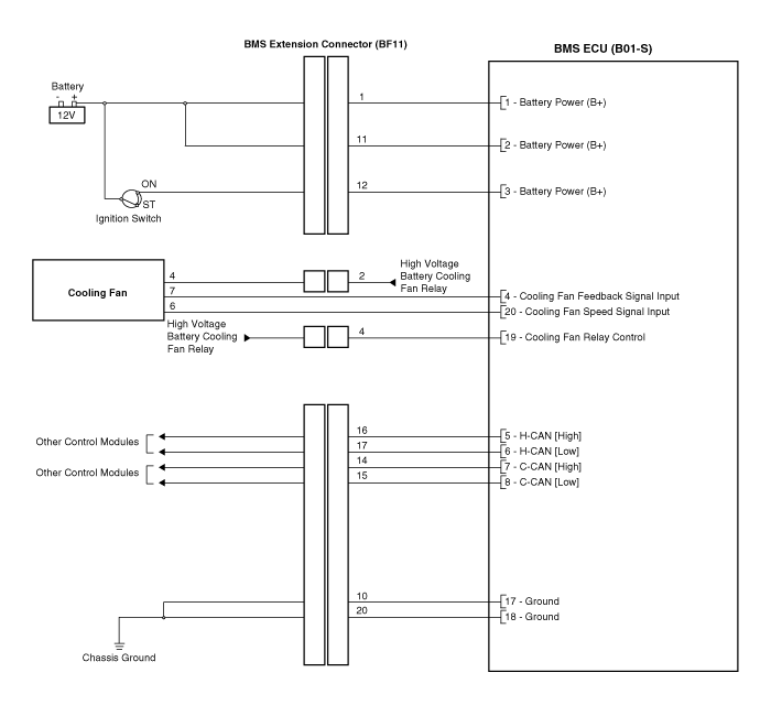
1
|
Battery Power (B+)
|
BMS Extension Connector BF11 (1)
|
2
|
Battery Power (B+)
|
BMS Extension Connector BF11 (11)
|
3
|
Battery Power (B+)
|
BMS Extension Connector BF11 (12)
|
4
|
Cooling fan feedback signal input
|
BMS Blower Motor
|
5
|
H-CAN [High]
|
Other Control Module
|
6
|
H-CAN [Low]
|
Other Control Module
|
7
|
P-CAN [High]
|
Other Control Module
|
8
|
P-CAN [Low]
|
Other Control Module
|
9
|
-
|
-
|
10
|
-
|
-
|
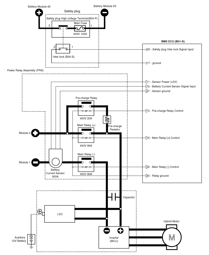
11
|
Sensor Power (+5V)
|
Battery Current Sensor [PRA]
|
12
|
Battery Current Sensor signal input
|
Battery Current Sensor [PRA]
|
13
|
-
|
-
|
14
|
-
|
-
|
15
|
Pre-Charge Relay Control
|
Pre-Charge Relay
|
16
|
Main Relay [+] Control
|
Main Relay [+]
|
17
|
Ground
|
Chassis Ground
|
18
|
Ground
|
Chassis Ground
|
19
|
Cooling Fan Relay Control
|
BMS Extension Connector BF11 (4)
|
20
|
Cooling Fan Speed signal input
|
BMS Blower Motor
|
21
|
-
|
-
|
22
|
-
|
-
|
23
|
-
|
-
|
24
|
Clash signal input
|
BMS Extension Connector BF11 (18)
|
25
|
Safety Plug Interlock signal input
|
Safety Plug
|
26
|
-
|
|
27
|
Sensor ground
|
Battery Current Sensor [PRA]
|
28
|
-
|
-
|
29
|
-
|
-
|
30
|
VPD Relay Control
|
VPD Relay
|
31
|
-
|
-
|
32
|
Main Relay [-] Control
|
Main Relay [-]
|
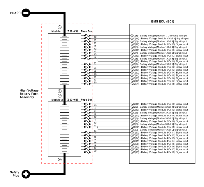
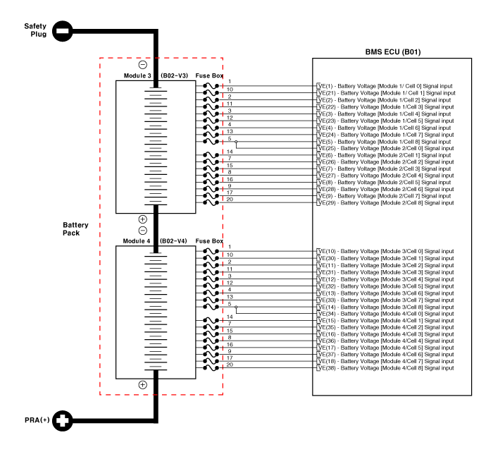
Module
|
Cell
|
Battery cell number displayed on KDS / GDS
|
Pins
|
1
|
1
|
1
|
B01-VC (4) and B01-VC (16)
|
2
|
2
|
B01-VC (16) and B01-VC (5)
|
3
|
3
|
B01-VC (5) and B01-VC (17)
|
4
|
4
|
B01-VC (17) and B01-VC (6)
|
5
|
5
|
B01-VC (6) and B01-VC (18)
|
6
|
6
|
B01-VC (18) and B01-VC (7)
|
7
|
7
|
B01-VC (7) and B01-VC (19)
|
8
|
8
|
B01-VC (19) and B01-VC (8)
|
9
|
9
|
B01-VC (20) and B01-VC (9)
|
10
|
10
|
B01-VC (9) and B01-VC (21)
|
11
|
11
|
B01-VC (21) and B01-VC (10)
|
12
|
12
|
B01-VC (10) and B01-VC (22)
|
13
|
13
|
B01-VC (22) and B01-VC (11)
|
14
|
14
|
B01-VC (11) and B01-VC (23)
|
15
|
15
|
B01-VC (23) and B01-VC (12)
|
16
|
16
|
B01-VC (12) and B01-VC (24)
|
2
|
1
|
17
|
B01-VD (18) and B01-VD (5)
|
2
|
18
|
B01-VD (5) and B01-VD (19)
|
3
|
19
|
B01-VD (19) and B01-VD (6)
|
4
|
20
|
B01-VD (6) and B01-VD (20)
|
5
|
21
|
B01-VD (20) and B01-VD (7)
|
6
|
22
|
B01-VD (7) and B01-VD (21)
|
7
|
23
|
B01-VD (21) and B01-VD (8)
|
8
|
24
|
B01-VD (8) and B01-VD (22)
|
9
|
25
|
B01-VD (9) and B01-VD (23)
|
10
|
26
|
B01-VD (23) and B01-VD (10)
|
11
|
27
|
B01-VD (10) and B01-VD (24)
|
12
|
28
|
B01-VD (24) and B01-VD (11)
|
13
|
29
|
B01-VD (11) and B01-VD (25)
|
14
|
30
|
B01-VD (25) and B01-VD (12)
|
15
|
31
|
B01-VD (12) and B01-VD (26)
|
16
|
32
|
B01-VD (26) and B01-VD (13)
|
3
|
1
|
33
|
B01-VE (1) and B01-VE (21)
|
2
|
34
|
B01-VE (21) and B01-VE (2)
|
3
|
35
|
B01-VE (2) and B01-VE (22)
|
4
|
36
|
B01-VE (22) and B01-VE (3)
|
5
|
37
|
B01-VE (3) and B01-VE (23)
|
6
|
38
|
B01-VE (23) and B01-VE (4)
|
7
|
39
|
B01-VE (4) and B01-VE (24)
|
8
|
40
|
B01-VE (24) and B01-VE (5)
|
9
|
41
|
B01-VE (25) and B01-VE (6)
|
10
|
42
|
B01-VE (6) and B01-VE (26)
|
11
|
43
|
B01-VE (26) and B01-VE (7)
|
12
|
44
|
B01-VE (7) and B01-VE (27)
|
13
|
45
|
B01-VE (27) and B01-VE (8)
|
14
|
46
|
B01-VE (8) and B01-VE (28)
|
15
|
47
|
B01-VE (28) and B01-VE (9)
|
16
|
48
|
B01-VE (9) and B01-VE (29)
|
4
|
1
|
49
|
B01-VE (10) and B01-VE (30)
|
2
|
50
|
B01-VE (30) and B01-VE (11)
|
3
|
51
|
B01-VE (11) and B01-VE (31)
|
4
|
52
|
B01-VE (31) and B01-VE (12)
|
5
|
53
|
B01-VE (12) and B01-VE (32)
|
6
|
54
|
B01-VE (32) and B01-VE (13)
|
7
|
55
|
B01-VE (13) and B01-VE (33)
|
8
|
56
|
B01-VE (33) and B01-VE (14)
|
9
|
57
|
B01-VE (34) and B01-VE (15)
|
10
|
58
|
B01-VE (15) and B01-VE (35)
|
11
|
59
|
B01-VE (35) and B01-VE (16)
|
12
|
60
|
B01-VE (16) and B01-VE (36)
|
13
|
61
|
B01-VE (36) and B01-VE (17)
|
14
|
62
|
B01-VE (17) and B01-VE (37)
|
15
|
63
|
B01-VE (37) and B01-VE (18)
|
16
|
64
|
B01-VE (18) and B01-VE (38)
|
 Troubleshooting
 BMS ECU Repair procedures
