Kia Niro: AHB(Active Hydraulic Boost) System / Stop Lamp Switch Schematic diagrams
Kia Niro 2017 (DE HEV) Service Manual / Brake System / AHB(Active Hydraulic Boost) System / Stop Lamp Switch Schematic diagrams
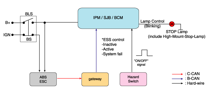
| Schematic Diagram |
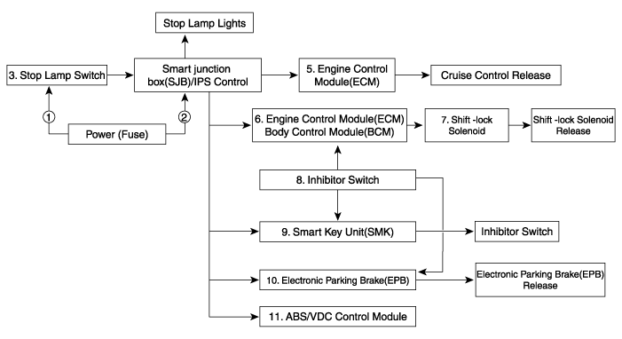
| System circuit diagram |
| Terminal function |

|
Teminal |
Description |
|
1 |
IGN1 |
|
2 |
Engine Control Module (ECM) |
|
3 |
B+ |
|
4 |
Stop Lmap |
 Stop Lamp Switch Components and components location
Components
1. Pedal stroke sensor
2. Stop lamp switch
3. Brake pedal arm
...
 Stop Lamp Switch Troubleshooting
Troubleshooting
1.
Part diagnosis
Items
Cause
Symptom
Switch fuse ...
Other information:
Kia Niro (DE HEV) Owners Manual: START/RUN
Not illuminated
To start the engine, depress the brake pedal and press the engine start/stop
button with the shift lever in the P (Park) or the N (Neutral) position. For your
safety, start the engine with the shift lever in the P (Park) position.
✽ NOTICE
If you press the engine start/sto ...
Kia Niro (DE HEV) Owners Manual: Phone
Select the [SETUP] button on the audio system ➟ Select [Phone].
Connections: Control pairing, deletion, connection and disconnection of
Bluetooth® devices.
Auto connection priority(Auto Connection Priority): Set the connection priority
of Bluetooth® devices when the vehicle is starte ...
© 2016-2024 www.kniro.net
