Kia Niro: Low Voltage DC/DC Converter (LDC) / Repair procedures
| Removal |
|

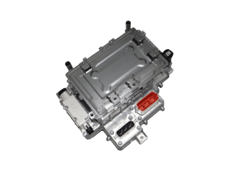
Hybrid Power Control Unit (HPCU)
| 1. |
Shut off the high voltage circuit. (Refer to Hybrid Control System - “High Voltage Shutoff Procedure”) |
| 2. |
Remove the air cleaner assembly and air duct. (Refer to Engine Mechanical System - "Air Cleaner") |
| 3. |
Remove the ECM & TCM bracket assembly. (Refer to Engine Control/Fuel System - "Engine Control Module") |
| 4. |
Drain the coolant of hybrid motor cooling system. (Refer to Hybrid Motor Cooling System - "Coolant") |
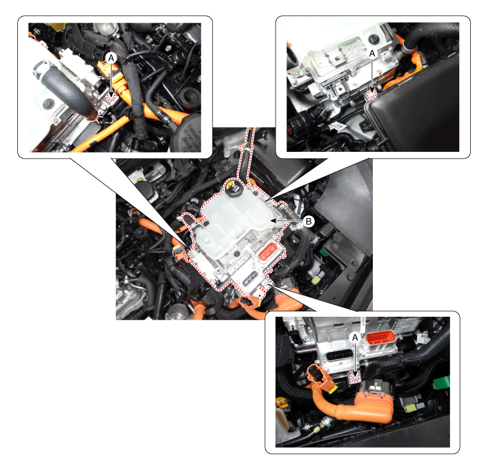
| 5. |
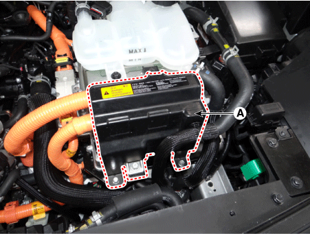
Remove the HPCU protector (A) after loosening the mounting bolts.
|
| 6. |
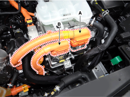
Disconnect the motor power cable connector (A) and HSG power cable connector (B).
|
| 7. |
Disconnect the power cable (A) [↔ High voltage battery system assembly] and power cable (B) [↔ HSG & Electric A/C compressor].
|

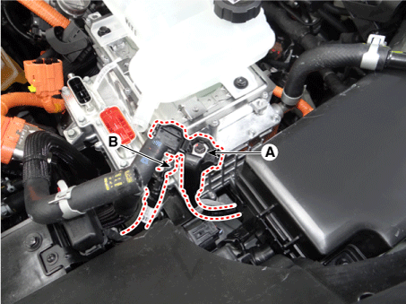
| 8. |
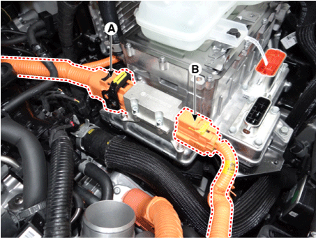
Disconnect the HCU & inverter (MCU) connector (A).
|
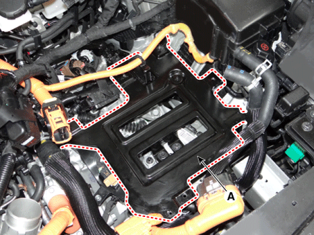
| 9. |
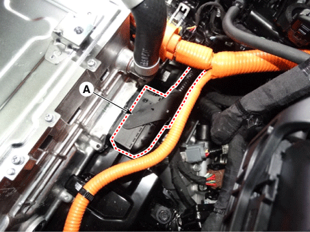
Disconnect the coolant outlet hose & pipe (A) after loosening the mounting bolt.
|
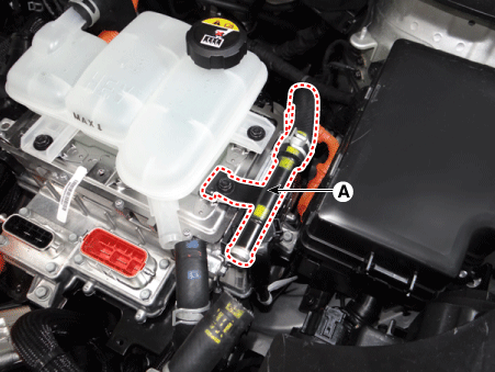
| 10. |
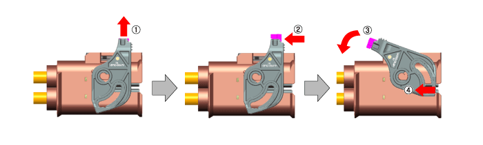
Disconnect the LDC power output cable (A) and LDC ground (-) cable (C) after loosening the mounting bolt and nut.
|
| 11. |
Remove the HPCU (B) after loosening the mounting bolts.
|
| 12. |
Remove the coolant hose & pipe (A) from the HPCU. |
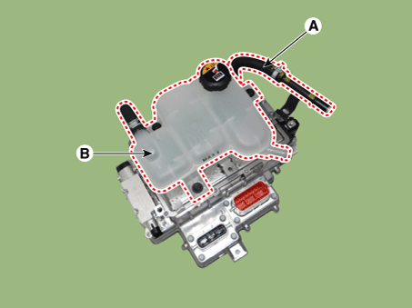
| 13. |
Remove the reservoir (B) after loosening the mounting bolts.
|
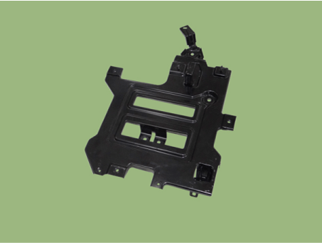
Hybrid Power Control Unit (HPCU) Tray
| 1. |
Remove the hybrid power control unit. (Refer to Hybrid Control System - "Hybrid Power Control Unit (HPCU)") |
| 2. |
Remove the hybrid power control unit tray (A) after loosening the mounting bolts.
|
| Installation |
|
| 1. |
Install the LDC in the reverse order of removal. |
| 2. |
Refill the hybrid motor cooling system coolant and perform air bleeding by using the KDS/GDS. (Refer to Hybrid Motor Cooling System - "Coolant") |
 Schematic diagrams
Schematic Diagram
...
 Power Cable
...
Other information:
Kia Niro (DE HEV) Owners Manual: Outside Temperature Gauge
This gauge indicates the current outside air temperatures by 1°C (1°F).
- Temperature range : -40°C~ 60°C (- 40°F ~ 140°F)
The outside temperature on the display may not change immediately like a general
thermometer to prevent the driver from being inattentive.
The temperature unit can ...
Kia Niro 2017 (DE HEV) Service Manual: Description and operation
Warning Lamp Activation
Warning Lamp Behavior after Ignition
On
As soon as the operating voltage is applied to the SRSCM ignition input, the
SRSCM activates the warning lamp for a LED lamp check.
The lamp shall turn on for 6 seconds during the initialization phase ...
