
Kia Niro: Ignition Switch / Repair procedures
| Inspection |
| 1. |
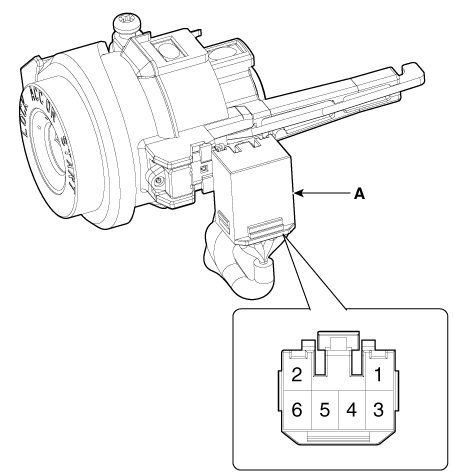
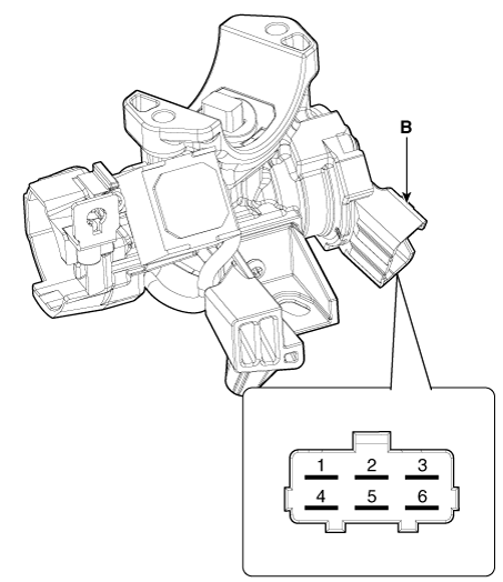
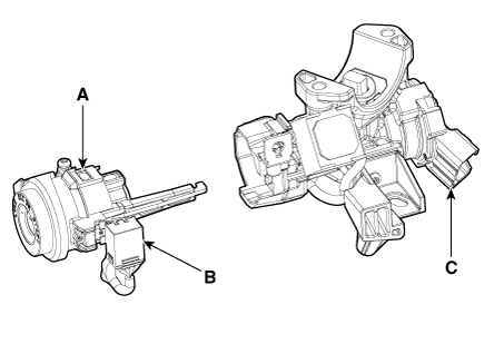
Disconnect the key warning switch connector (A) and ignition switch connector (B) from the steering column.
|
| 2. |
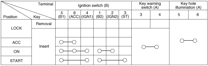
Check for continuity between the terminals. |
| 3. |
If continuity is not specified, replace the switch.
|
| Removal |
| 1. |
Disconnect the negative (-) battery terminal. |
| 2. |
Remove the crash pad lower panel. (Refer to Body - "Crash Pad Lower Panel") |
| 3. |
Remove the steering column upper and lower shroud panel. (Refer to Body - "Steering Column Shroud Panel") |
| 4. |
Remove the multifunction switch. (Refer to Body Electrical System - "Multifunction Switch") |
| 5. |
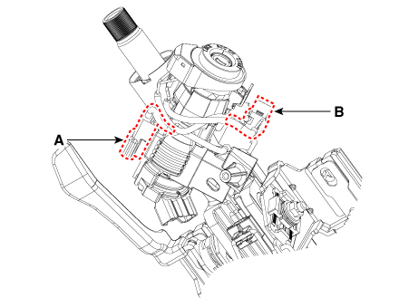
Remove the ignition switch connector (A) and key warning / immobilizer connector (B).
|
| 6. |
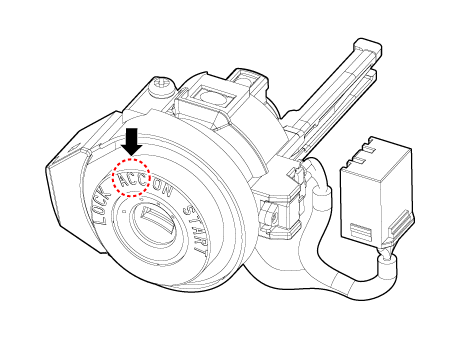
Insert key and turn it to ACC position.
|
| 7. |
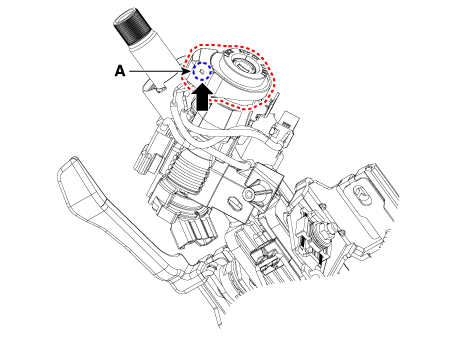
Pushing lock pin (A) with the awl.
|
| 8. |
Remove the key lock cylinder (A).
|
| 9. |
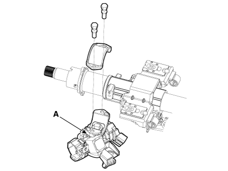
Remove the ignition switch (A) after loosening the mounting bolts.
|
| Installation |
|

| 1. |
Install the ignition switch. |
| 2. |
Install the key lock cylinder. |
| 3. |
Connect the ignition switch connector and key warning / immobilizer connector. |
| 4. |
Install the multifunction switch. |
| 5. |
Install the steering column upper and lower shroud panel. |
| 6. |
Install the crash pad lower panel. |
| 7. |
Connect the negative (-) battery terminal. |
 Ignition Switch
...

Other information:
Kia Niro (DE HEV) Owners Manual: Seat belt restraint system
WARNING
For maximum restraint system protection, the seat belts must always be
used whenever the vehicle is moving.
Seat belts are most effective when seatbacks are in the upright position.
Children age 12 and under must always be properly restrained. If a child
over 12 must be seated ...
Kia Niro (DE HEV) Owners Manual: Temperature control
The temperature will increase to the maximum by turning the knob to the extreme
right.
The temperature will decrease to the minimum by turning the knob to the extreme
left.
When turning the knob, the temperature will increase or decrease by 0.5°C/1°F.
When set to the lowest temperature s ...
