Kia Niro: Fuses And Relays / Relay Box (Passenger Compartment) Repair procedures
| Fuse Inspection |
| 1. |
Check that the fuse holders are loosely held and that the fuses are securely fixed by the holders. |
| 2. |
Check that each fuse circuit has the exact fuse capacity. |
| 3. |
Check the fuses for any damage.
|
| Diagnosis with KDS/GDS |
| 1. |
In the body electrical system, failure can be quickly diagnosed by using the vehicle diagnostic system (KDS/GDS). The diagnostic system (KDS/GDS) provides the following information.
|
| 2. |
Select the 'Car model' and the 'Smart Junction Block (SJB)' to be checked in order to check the vehicle with the tester. |
| 3. |
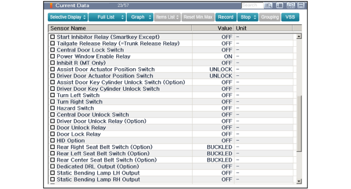
Select the 'Current Data' menu to search the current state of the input/output data.
|
| 4. |
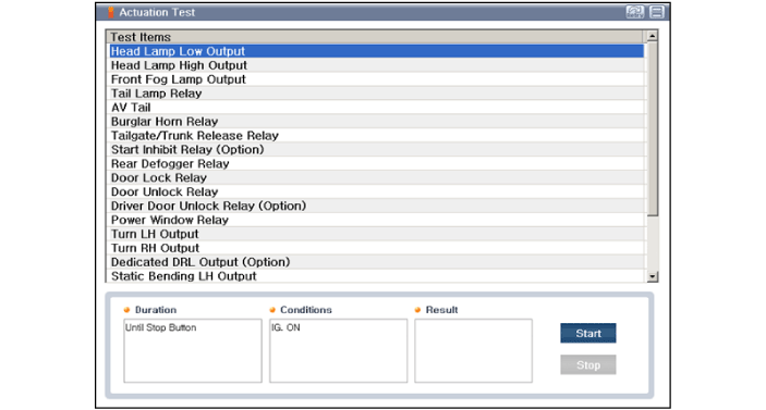
To forcibly actuate the input value of the module to be checked, select option 'Actuation Test'
|
| 5. |
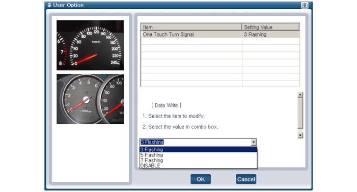
If you want to change user option, select "user option".
|
| Removal |
[Integrated Gateway & Power control Module (IGPM)]
| 1. |
Disconnect the negative (-) battery terminal. |
| 2. |
Remove the crash pad lower panel. (Refer to Body - "Crash Pad Lower Panel") |
| 3. |
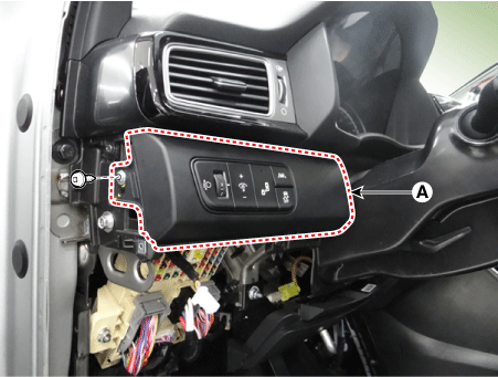
Remove the crash pad side switch (A) after loosening the mounting screw.
|
| 4. |
Disconnect the crash pad side switch connector (A).
|
| 5. |
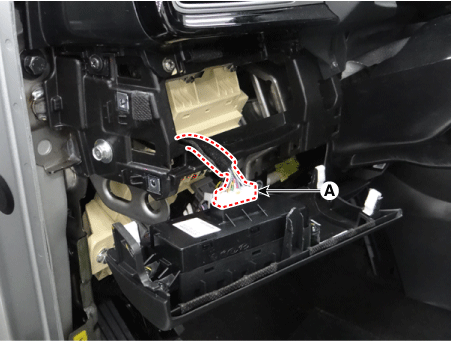
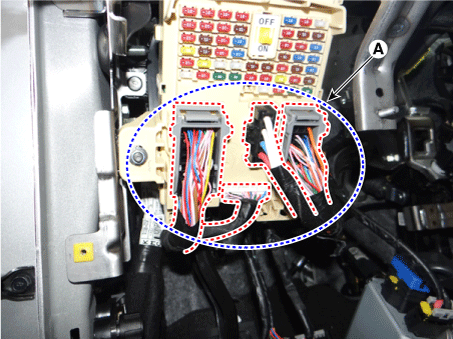
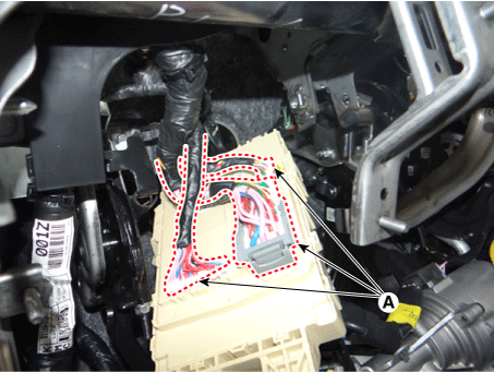
Disconnect the connectors (A) from the fuse side of the IGPM.
|
| 6. |
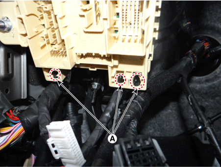
Remove the mounting clips (A).
|
| 7. |
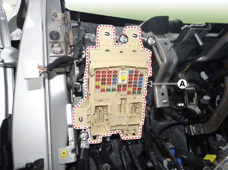
Remove the IGPM (A) after loosening the mounting nuts.
|
| 8. |
Disconnect the connectors (A) from the back of the IGPM.
|
[ICM Relay Block]
| 1. |
Disconnect the negative (-) battery terminal. |
| 2. |
Remove the main crash pad assembly. (Refer to Body - " Main Crash Pad Assembly") |
| 3. |
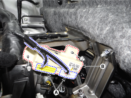
Disconnect the ICM relay block connectors (A) |
| 4. |
Remove the ICM relay block (B) after loosening the mounting nuts.
|
| Installation |
[Integrated Gateway & Power Control Module (IGPM)]
| 1. |
Connect the IGPM connectors. |
| 2. |
Install the IGPM. |
| 3. |
Install the crash pad side switch. |
| 4. |
Install the crash pad lower panel. |
| 5. |
Connect the negative (-) battery terminal. |
| 6. |
Check that all systems operate properly. |
[ICM Relay Block]
| 1. |
Install the ICM relay block. |
| 2. |
Connect the ICM relay block connectors. |
| 3. |
Install the main crash pad assembly. |
| 4. |
Connect the negative (-) battery terminal. |
| 5. |
Check that all systems operate properly. |
 Relay Box (Passenger Compartment) Description and operation
Description
Communication Network
Diagram
Abbreviation
Expalnation
AAF
Active Air Flap
ACU
Airb ...
Other information:
Kia Niro 2017 (DE HEV) Service Manual: Lane Keeping Assist System (LKAS) Unit Repair procedures
Removal
When replacing the LKAS switch, check that the symbol mark in the cluster
operates normally by pressing the ON/OFF switch.
1.
Disconnect the negative (-) battery terminal. ...
Kia Niro 2017 (DE HEV) Service Manual: Components and components location
Components Location
[Fuel Tank Assembly]
1. Fuel Tank
2. Fuel Pump Assembly
3. Canister
4. Fuel Tank Air Filter
5. Fuel Tank Band
6. Fuel Filler Hose
7. Leveling Hose
8. Ventilation hose
9. Vapor Tube
10. Fuel Pum ...


