Kia Niro: AHB(Active Hydraulic Boost) System / Pressure Source Unit Repair procedures
| Removal |
| 1. |
Turn ignition switch OFF and disconnect the negative (-) battery terminal. |
| 2. |
Remove the air cleaner assembly. (Refer to Engine Mechanical System - "Air Cleaner") |
| 3. |
Remove the brake fluid from the reservoir . |
| 4. |
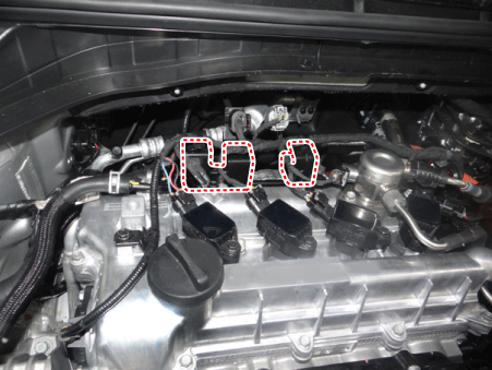
Remove the connector and wire ring bracket.
|
| 5. |
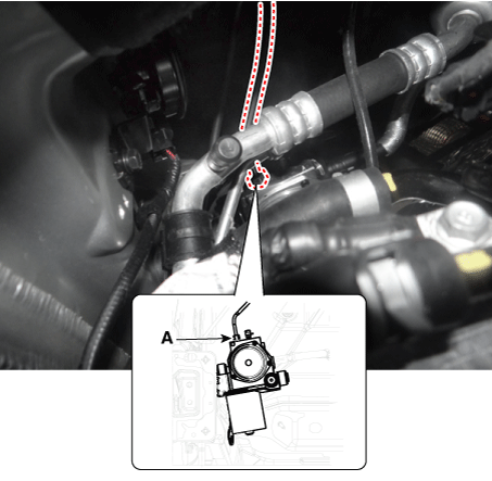
Loosen the pressure source unit (PSU) flare nut (A) and then remove the tube.
|
| 6. |
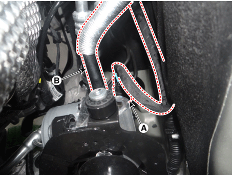
Disconnect the pressure source unit (PSU) connector (A) and hose (B).
|

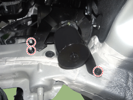
| 7. |
Remove the sub frame. (Refer to Suspension System - "Sub Frame") |
| 8. |
Loosen the nuts and bolt and then remove the pressure source (PSU).
|
| Installation |
| 1. |
Installation is the reverse of removal. |
| 2. |
Check the brake pedal operation. |
| 3. |
After filling the brake fluid in the reservoir, perform the air bleed. (Refer to the Brake system - "Brake Bleeding Procedure") |
| 4. |
Conduct the pedal traval sensor (PTS) calibration. (Refer to the Brake System - "Brake Pedal") |
| 5. |
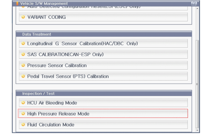
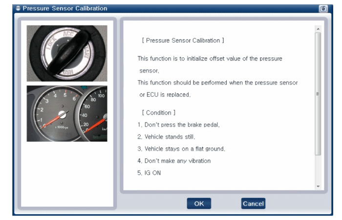
Conduct the pressure sensor calibration. |
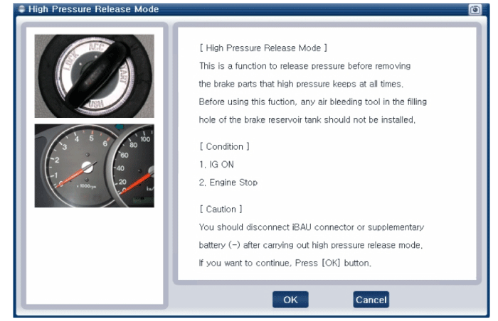
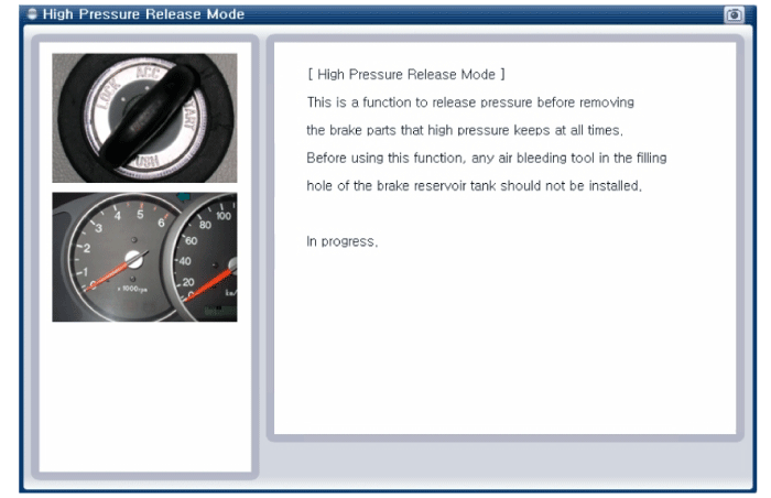
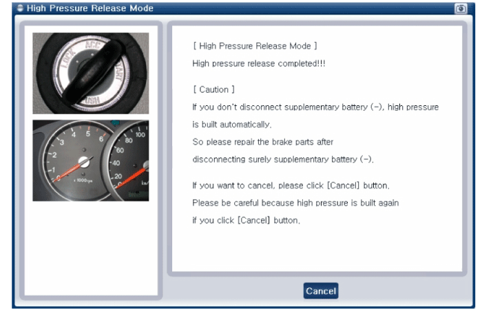
| Diagnostic Procedure Using a Diagnostic Instrument |
The following section describes how to diagnose faults using a diagnostic instrument.
| 1. |
Connect the diagnostic instrument to the self-diagnostic connector (16-pin) beneath the crash pad on the side of driver's seat, and then turn on the ignition to activate the diagnostic instrument. |
| 2. |
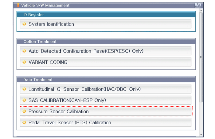
In the GDS Vehicle Type Selection menu, select "Vehicle Type" and "Brake/VDC/AHB" System, and then opt for "OK." Pressure Sensor Calibration
|
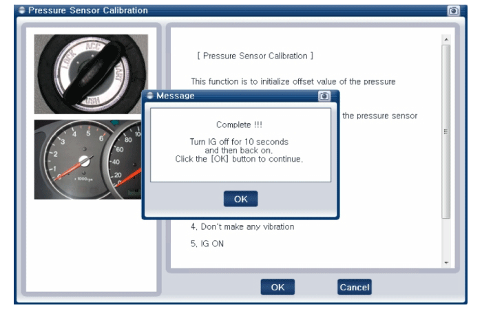
| 3. |
Turn ignition switch off and on after calibration procedure. |
| 4. |
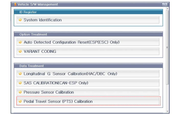
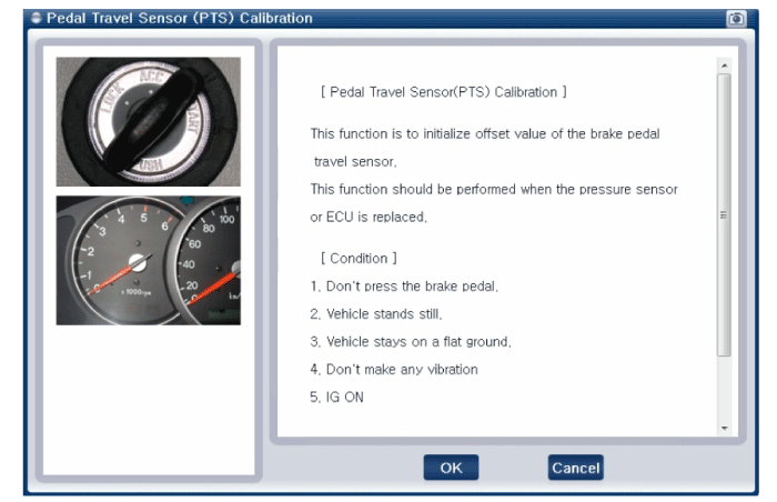
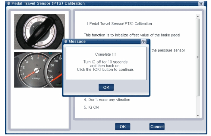
Confirm success of calibration. Pedal Travel Sensor (PTS) Calibration
|
 Pressure Source Unit Components and components location
Components
1. Pressure Source Unit (PSU)
2. Motor
3. Filler adapter
4. Accumulator
5. Bracket
...
 Brake Line Components and components location
Components
...
Other information:
Kia Niro (DE HEV) Owners Manual: When the hybrid vehicle shuts off
When the high voltage battery or 12- volt battery discharges, or fuel tank is
empty, the hybrid system may not operate.
If the Hybrid system stops operating while the vehicle is moving, reduce the
vehicle speed gradually. Pull your vehicle off the road in a safe area, and shift
the transmissi ...
Kia Niro 2017 (DE HEV) Service Manual: Front Driveshaft Components and components location
Component location
1. Inner shaft bearing bracket
2. Drive shaft (RH)
3. Drive shasft (LH)
...
