Kia Niro: Dual Clutch Transmission Control System / DCT Control Module (TCM) Schematic diagrams
Kia Niro 2017 (DE HEV) Service Manual / DCT(Dual Clutch Transmission) System / Dual Clutch Transmission Control System / DCT Control Module (TCM) Schematic diagrams
| TCM Connector |
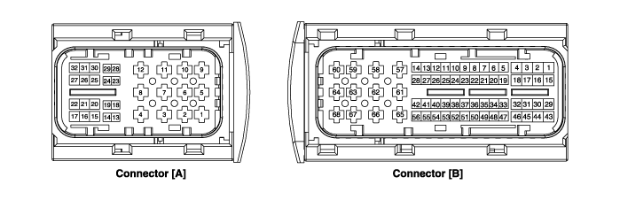
| TCM Terminal Function |
Connector [A]
|
Pin |
Description |
Pin |
Description |
|
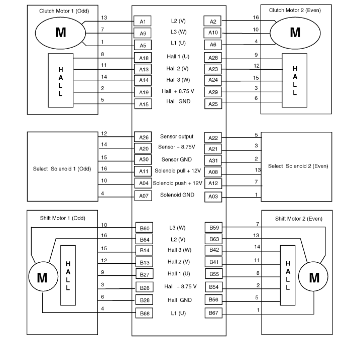
1 |
Clutch actuator (Clutch motor 1 (Odd)_Phase V) |
15 |
Clutch actuator (Clutch motor 1 (Odd)_Sensor ground) |
|
2 |
Clutch actuator (Clutch motor 2 (Even)_Phase V) |
18 |
Clutch actuator (Clutch motor 1 (Odd)_Hall 1) |
|
3 |
Select actuator (Select solenoid 2 (Even)_ ground) |
19 |
Clutch actuator (Clutch motor 1 (Odd)_Supply) |
|
4 |
Select actuator (Select solenoid 1 (Odd)_Push) |
20 |
Select actuator (Select solenoid 1 (Odd)_Sensor supply) |
|
5 |
Clutch actuator (Clutch motor 1 (Odd)_Phase U) |
21 |
Select actuator (Select solenoid 2 (Even)_Sensor supply) |
|
6 |
Clutch actuator (Clutch motor 2 (Even)_Phase U) |
22 |
Select actuator (Select solenoid 2 (Even)_Sensor ouput) |
|
7 |
Select actuator (Select solenoid 1 (Odd)_ ground) |
23 |
Clutch actuator (Clutch motor 2 (Even)_Hall 2) |
|
8 |
Select actuator (Select solenoid 2 (Even)_ Pull) |
24 |
Clutch actuator (Clutch motor 2 (Even)_Hall 3) |
|
9 |
Clutch actuator (Clutch motor1 (Odd)_Phase W) |
25 |
Clutch actuator (Clutch motor 2 (Even)_Sensor ground) |
|
10 |
Clutch actuator (Clutch motor 2 (Even)_Phase W) |
26 |
Select actuator (Select solenoid 1 (Odd)_Sensor output) |
|
11 |
Select actuator (Shifts olenoid 1 (Odd)_Pull) |
28 |
Clutch actuator (Clutch motor 2 (Even)_Hall 1) |
|
12 |
Select actuator (Shift solenoid 2 (Even)_Push) |
29 |
Clutch actuator (Clutch motor 2 (Even)_Sensor supply) |
|
13 |
Clutch actuator (Clutch motor 1 (Odd)_Hall 2) |
30 |
Select actuator (Select solenoid 1 (Odd)_Sensor ground) |
|
14 |
Clutch actuator (Clutch motor (Odd)_Hall 3) |
31 |
Select actuator (Select solenoid 2 (Even)_Sensor ground) |
Connector [B]
|
Pin |
Description |
Pin |
Description |
|
3 |
ON / START input |
42 |
Shift actuator (Shift motor 2 (Even) _Hall 3) |
|
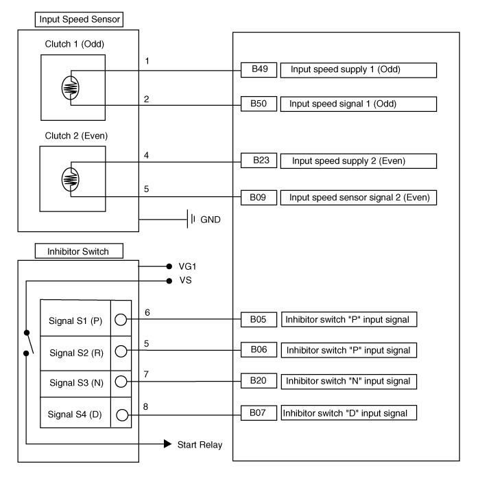
5 |
Inhibitor switch "P" input signal |
43 |
Inhibitor switch "M" Input signal |
|
6 |
Inhibitor switch "R" input signal |
44 |
CAN1 communication port1 High |
|
7 |
Inhibitor switch "D" input signal |
45 |
CAN1 communication port1 low |
|
8 |
Manual mode "Down" switch |
48 |
Flex ray high (BP) |
|
9 |
Input speed sensor signal 2 (Even) |
49 |
Input speed supply 1 (Odd) |
|
13 |
Shift actuator (Shift motor 1 (Odd) _Hall 2) |
50 |
Input speed signal 1 (Odd) |
|
14 |
Shift actuator (Shift motor 1 (Odd) _Hall 3) |
54 |
Shift actuator (Shift motor 2 (Even) _Sensor supply) |
|
17 |
Battery power low VBD |
55 |
Shift actuator (Shift motor 2 (Even) _Hall 1) |
|
19 |
Manual mode "Select" switch |
56 |
Shift actuator (Shift motor 2 (Even) _Sensor ground) |
|
20 |
Inhibitor switch "N" input signal |
57 |
Power ground 1 for high current modules |
|
21 |
Manual mode "Up" switch |
58 |
Power ground 2 for high current modules |
|
23 |
Input speed supply 2 (Even) |
59 |
Shift actuator (Shift motor 2 (Even)_Phase W) |
|
24 |
5V spare supply output |
60 |
Shift actuator (Shift motor 1 (Odd)_Phase W) |
|
26 |
Shift actuator (Shift motor 1 (Odd)_Sensor supply |
61 |
Power
ground 3 for high current modules |
|
27 |
Shift actuator (Shift motor 1 (Odd)_Hall 1) |
63 |
Shift Actuator (Shift motor 2 (Even)_Phase V) |
|
28 |
Shift actuator (Shift motor 1 (Odd)_Sensor ground) |
64 |
Shift Actuator (Shift Motor 1 (Odd)_Phase V) |
|
30 |
CAN2 communication port2 High |
65 |
Motor supply voltage 1 from direct battery |
|
31 |
CAN2 communication port2 Low |
66 |
Motor supply voltage 2 from direct battery |
|
34 |
Flex ray bus, BM |
67 |
Shift actuator (Shift motor 2 (Even)_Phase U) |
|
41 |
Shift actuator (Shift motor 2 (Even) _Hall 2) |
68 |
Shift actuator (Shift motor 1 (Odd)_Phase U) |
| Circuit Diagram |
 DCT Control Module (TCM) Components and components location
Conponent Location
1. DCT Control Module (TCM)
...
 DCT Control Module (TCM) Repair procedures
Inspection
1.
TCM ground circuit test : Measure the resistance between TCM and chassis
ground. (Inspect the terminal connected to the chassis ground with the back
o ...
Other information:
Kia Niro 2017 (DE HEV) Service Manual: Battery Pack Assembly Specifications
Specification
Battery Pack Assembly
[General Specification]
Item
Specification
Remarks
Number of Cells
16 Cells × 4 Modules [64 Cell]
1 Cell = 3.75 V
Type
LiPB (Lithium ion P ...
Kia Niro 2017 (DE HEV) Service Manual: Front Disc Brake Repair procedures
Removal
1.
Remove the wheel & tire.
2.
Remove the caliper hose bracket bolt (A).
Tightening torque :
8.8 - 13.7 N·m (0.9 - 1.4 kgf·m, 6.5 - 10.1 lb·ft)
3.
Loosen t ...
© 2016-2024 www.kniro.net
