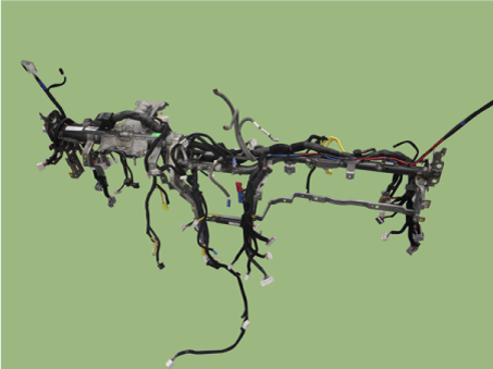
Kia Niro: Crash Pad / Cowl Cross Bar Assembly Repair procedures
| Replacement |
Put on gloves to protect your hands. |
|
| 1. |
Remove the cowl top cover. (Refer to "Cowl Top Cover") |
| 2. |
Remove the front wiper motor. (Refer to Body Electrical System - "Front Wiper Motor") |
| 3. |
Remove the main crash pad assembly. (Refer to Crash Pad - "Main Crash Pad Assembly") |
| 4. |
Remove the cowl side trim. (Refer to Interior Trim - "Cowl Side Trim") |
| 5. |
Disconnect the steering column connectors. (Refer to Steering System - "Steering Column and Shaft") |
| 6. |
Lower the steering column after loosening the mounting bolts. (Refer to Steering System - "Steering Column and Shaft") |
| 7. |
Remove the accelerator pedal. (Refer to Engine Control System - "Accelerator Position Sensor (APS)") |
| 8. |
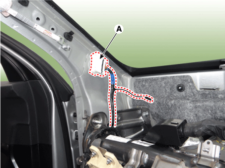
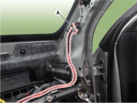
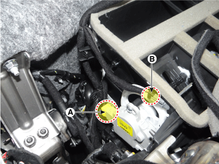
Disconnect the connector (A) and the mounting clips in the front pillar. [Driver side]
[Passenger side]
|
| 9. |
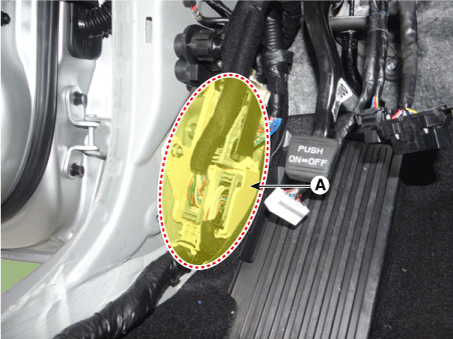
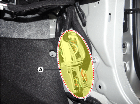
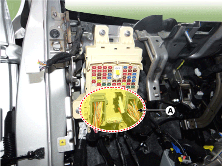
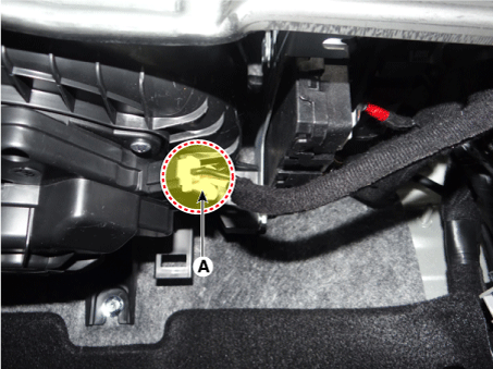
Disconnect the multi box connectors (A). [Driver side]
[Passenger side]
|
| 10. |
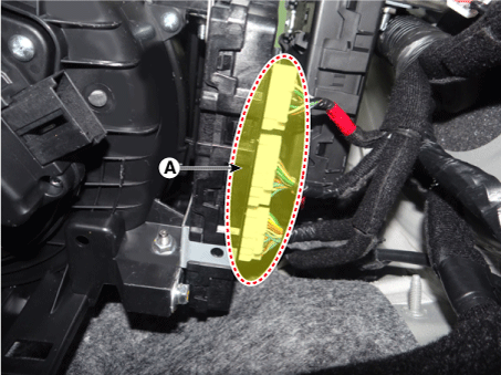
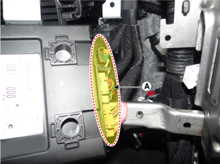
Disconnect the passenger compartment junction box connectors (A).
|
| 11. |
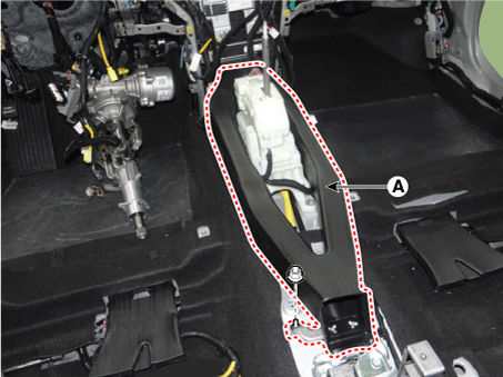
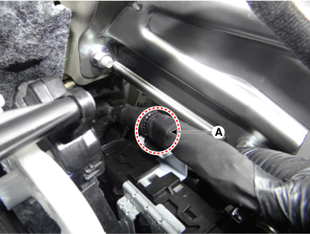
Remove the rear air duct (A) after loosening the nut.
|
| 12. |
Disconnect the connector (A) and wiring mounting clip.
|
| 13. |
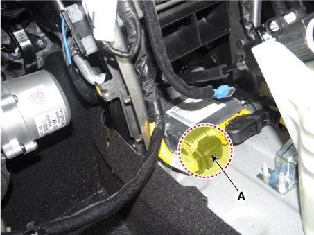
Disconnect the airbag control module (SRSCM) connector (A) and wiring mounting clip.
|
| 14. |
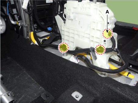
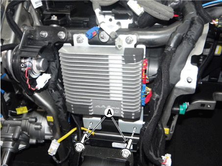
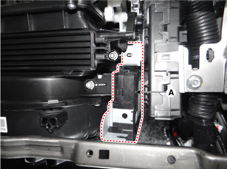
Loosen the external amplifier mounting bolts (A).
|
| 15. |
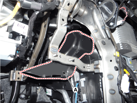
Separate the shower duct (A).
|
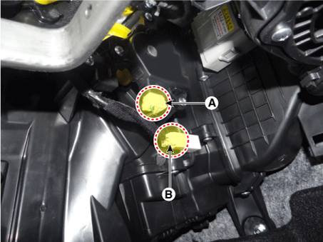
| 16. |
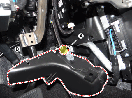
Remove the shower duct (B) after disconnecting the connector (A).
|
| 17. |
Disconnect the temperature actuator connector (A).
|
| 18. |
Disconnect the mode actuator connector (A), duct sensor (B) and wiring mounting clip.
|
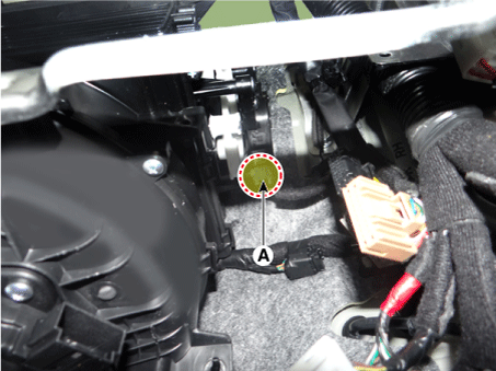
| 19. |
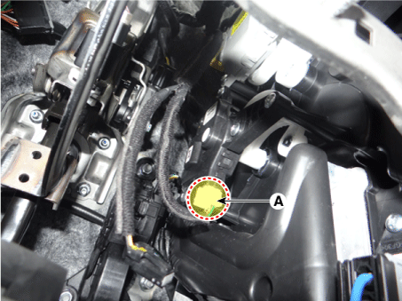
Disconnect the blower motor connector (A).
|
| 20. |
Disconnect the BCM unit connectors (A).
|
| 21. |
Separate the BCM unit (A) after loosening the bolts and nuts.
|
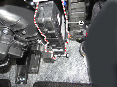
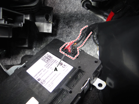
| 22. |
Remove the BCM unit after disconnecting the connectors (A).
|
| 23. |
Disconnect the wiring mounting mounting clip (A).
|
| 24. |
Separate the smart key unit (A) after loosening the bolt.
|
| 25. |
Remove the smart key unit after disconnecting the connectors (A).
|
| 26. |
Disconnect the intake actuator (A).
|
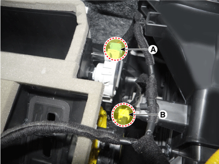
| 27. |
Disconnect the passenger side temperature actuator (A) & evaporator temperature sensor connectors (B) and then disconnect the wiring mounting clip.
|
| 28. |
Disconnect the auto defogging connector (A) & passenger side mode actuator connectors (B) and then disconnect the wiring mounting clip.
|
| 29. |
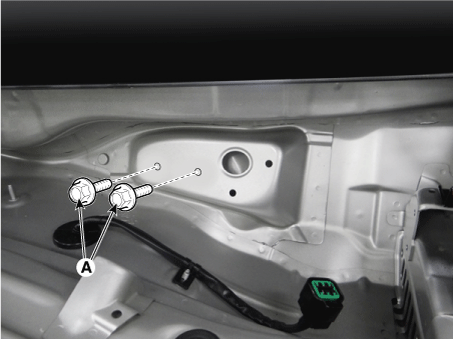
Loosen the cowl cross bar mounting bolts (A).
|
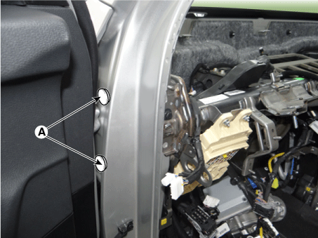
| 30. |
Remove the cowl cross bar mounting bolt cap (A).
|
| 31. |
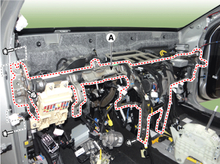
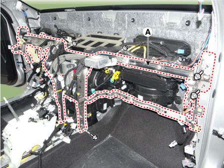
Remove the cowl cross bar assembly (A) after loosening the mounting bolts & nuts. [Driver Side]
[Passenger Side]
|
| 32. |
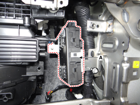
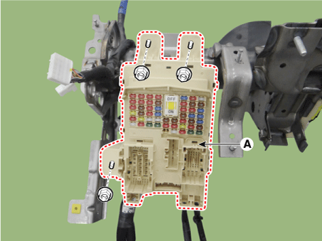
Remove the smart junction block (SJB) (A) after loosening the mounting nuts.
|
| 33. |
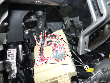
Remove the smart junction block (SJB) after disconnecting the connectors (A).
|
| 34. |
Remove the smart key antenna (A) after removing the connectors & nuts. |
| 35. |
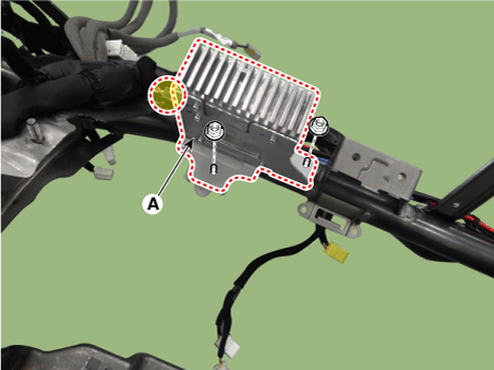
Remove the external amplifier (A) after removing the connectors & nuts.
|
| 36. |
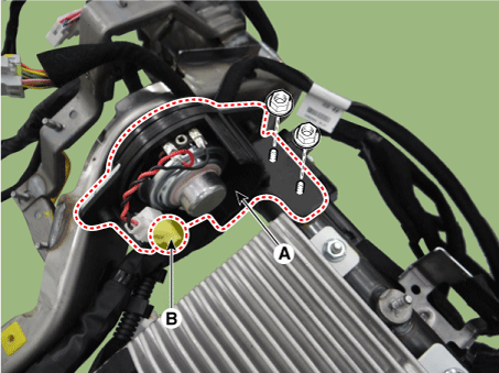
Remove the cluster speaker (A) after removing the connectors (B) & nuts.
|
| 37. |
Remove the main wiring from the cowl cross bar.
|
| 38. |
Install in the reverse order of removal.
|
 Cowl Cross Bar Assembly Components and components location
Component Location
1. Cowl cross bar assembly
...
 Fender
...
Other information:
Kia Niro 2017 (DE HEV) Service Manual: Engine Oil Repair procedures
Oil And Filter Replacement
•
Prolonged and repeated contact with mineral oil will result in
the removal of natural fats from the skin, leading to dryness, irritation
and dermatitis ...
Kia Niro 2017 (DE HEV) Service Manual: Components and components location
Components
1. Pressure Source Unit (PSU)
2. Integrated Brake Actuation Unit (IBAU)
3. Front wheel speed sensor
4. Rear wheel speed sensor
...


