Kia Niro: High Voltage Battery System / Battery Pack Assembly Repair procedures
| • |
Be sure to read and follow the “General Safety Information and
Caution” before doing any work related with the high voltage system.
Failure to follow the safety instructions may result in serious
electrical injuries.
|
| • |
Be sure to shut off the high voltage before doing any work related
with the high voltage system(Refer to "High Voltage Shut-off Procedure").
Failure to follow the safety instructions may result in serious
electrical injuries.
|
|
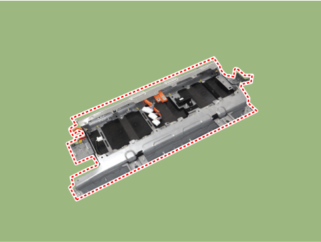
| 1. |
Remove the high voltage battery system assembly.
(Refer to High Voltage Battery System - "Removal")
|
| 2. |
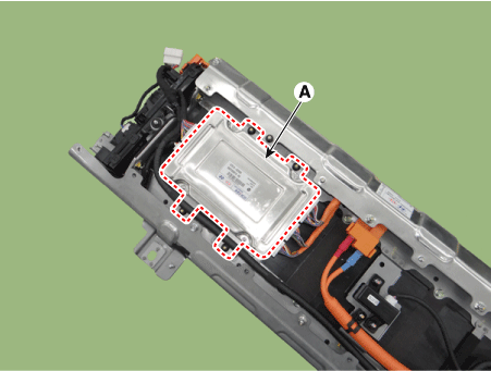
Remove the BMS ECU after loosening the mounting nuts.
|
BMS ECU mounting nut :
7.8 - 11.8 N·m (0.8 - 1.2 kgf·m, 5.8 - 8.7 lb·ft)
|
|
| 3. |
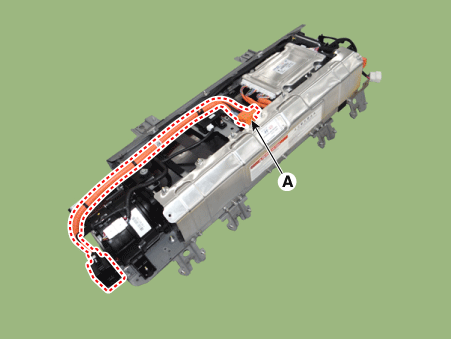
Remove the safety plug cable (A) after loosening the mounting bolts and
nut.
|
| 4. |
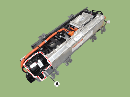
Remove the cooling fan (A) after loosening the mounting bolt and nuts.
|
| 5. |
Remove the BMS ECU extension wiring harness (A).
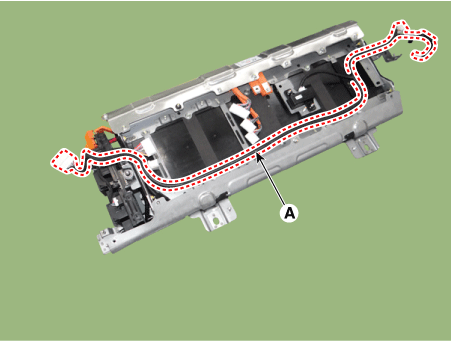
|
| 6. |
Remove the power relay assembly (A) after loosening the mounting nuts.
|
Power relay assembly mounting nut :
7.8 - 11.8 N·m (0.8 - 1.2 kgf·m, 5.8 - 8.7 lb·ft)
|
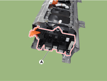
|
| • |
Be sure to read and follow the “General Safety Information and
Caution” before doing any work related with the high voltage system.
Failure to follow the safety instructions may result in serious
electrical injuries.
|
| • |
Be sure to shut off the high voltage before doing any work related
with the high voltage system(Refer to "High Voltage Shut-off Procedure").
Failure to follow the safety instructions may result in serious
electrical injuries.
|
|
| 1. |
Install the high voltage battery pack assembly in the reverse order of
removal.
|
| [Battery Pack Assembly Troubleshooting
Chart] |
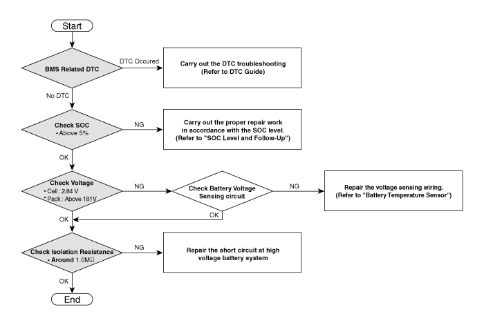
| • |
For SOC check, refer to “SOC Inspection”
|
| • |
For voltage check, refer to “Battery Voltage Inspection”
|
| • |
For battery voltage sensing circuit, refer to "Voltage Sensing
Circuit Inspection"
|
| • |
For isolation resistance check, refer to “Isolation Resistance
Inspection”
|
|
| [SOC Level and Follow-up] |
SOC
|
Symptom
|
Warning Lamp
|
Follow-up
|
MIL
|
Service
|
Fuel
|
|
|
-
|
-
|
-
|
|
10 ~ 15%
|
| • |
Motor torque limite
(Acceleration delay)
|
|
-
|
-
|
ON
|
| • |
Refuel and check the SOC again
|
|
ON
|
-
|
-
|
| • |
Repair the MIL or Service Lamp related system
|
| • |
Charge the battery by starting the engine
|
|
ON
|
ON
|
-
|
-
|
ON
|
-
|
On
|
ON
|
ON
|
5 ~ 10%
|
|
-
|
-
|
ON
|
| • |
Refuel and check the SOC again
|
|
ON
|
-
|
-
|
| • |
Repair the MIL or Service Lamp related system
|
| • |
Charge the battery by starting the engine
|
|
ON
|
ON
|
-
|
-
|
ON
|
-
|
ON
|
ON
|
ON
|
0 ~5%
|
|
ON
|
-
|
-
|
| • |
Repair the MIL or Service Lamp related system
|
| • |
Start the engine with KDS/GDS to charge the battery
|
|
ON
|
ON
|
-
|
-
|
ON
|
-
|
ON
|
ON
|
ON
|
0% 이하
|
ON
|
-
|
-
|
| • |
Repair the MIL or Service Lamp related system
|
| • |
If necessary, Replace Battery Pack
|
|
| 1. |
Connect the KDS/GDS to the Data Link Connector (DLC).
|
| 2. |
Turn the ignition switch ON.
|
| 3. |
Check the SOC in GDS service data.
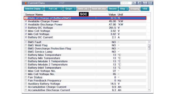
|
| [Battery Voltage Inspection] |
| 1. |
Connect the KDS/GDS to the Data Link Connector (DLC).
|
| 2. |
Turn the ignition switch ON.
|
| 3. |
Check the cell and pack voltage in GDS service data.
|
Cell Voltage: Above 2.84 V
Pack Voltage: Above 181 V
|
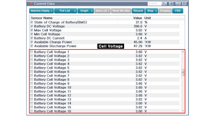
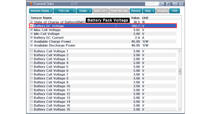
|
| [Voltage Sensing Circuit Inspection] |
| 1. |
Shut off the high voltage circuit (Refer to "High Voltage Shutoff Precedure").
|
| 2. |
Remove the battery temperature sensor (Refer to "Battery Temperature
Sensor").
|
| 3. |
Check the continuity of the wiring between the harness connectors of
the module and BMS ECU.
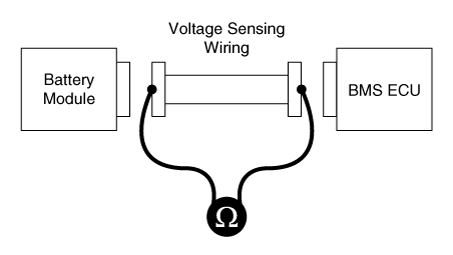
|
| 4. |
Connect the harness connectors to the BMS ECU.
|
| 5. |
For checking the short circuit to ground, measure resistance between
the module harness connectors and chassis ground.
|
Specification : 1MΩ or higher
|
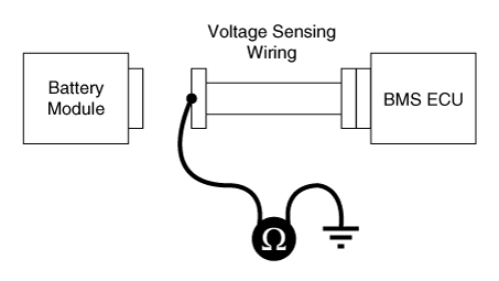
|
| [Isolation Resistance Inspection] |
| 1. |
Connect the KDS/GDS to the Data Link Connector (DLC).
|
| 2. |
Turn the ignition switch ON.
|
| 3. |
Check the isolation resistance in KDS/GDS service data.
|
Isolation Resistance: Around 1.0 MΩ
|
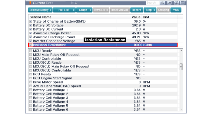
|
Specification
Battery Pack Assembly
[General Specification]
Item
Specification
Remarks
Number of Cells
16 Cells × 4 ...
Specification
Power Relay Assembly
(PRA)
Item
Specification
Rated Voltage (V)
240
Rated Current (A)
...


 Battery Pack Assembly Specifications
 Power Relay Assembly (PRA) Specifications


