
Kia Niro: Tires/Wheels / Alignment Repair procedures
| Front wheel alignment |
When using a commercially available computerized wheel alignment equipment to inspect the front wheel alignment, always position the vehicle on a level surface with the front wheels facing straight ahead. Prior to inspection, make sure that the front suspension and steering system are in normal operating condition and that the tires are inflated to the specified pressure. |

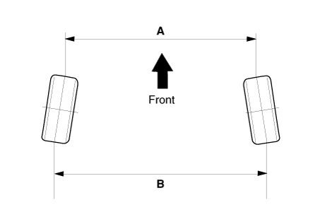
Toe
|
B - A > 0: Toe in (+) B - A < 0: Toe out (-) |
Toe adjustment
| 1. |
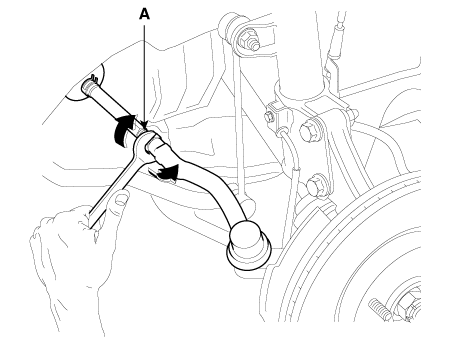
Loosen the tie rod end lock nut. |
| 2. |
Remove the bellows clip to prevent the bellows from being twisted. |
| 3. |
Adjust the toe by screwing or unscrewing the tie rod. Toe adjustment should be made by turning the right and left tie rods by the same amount.
|
| 4. |
When completing the toe adjustment, install the bellows clip and tighten the tie rod end lock nut to specified torque.
|
| 5. |
Perform the Steering Angle Sensor calibration.
|
Camber and Caster
Camber and Caster are pre-set at the factory, so they do not need to be adjusted. If the camber and caster are not within the standard value, replace or repair the damaged parts and then inspect again.
|
Camber angle : -0.4°±0.5° |
|
Caster angle : 4.4°±0.5° |
| Rear wheel alignment |
When using a commercially available computerized wheel alignment equipment to inspect the rear wheel alignment, always position the vehicle on a level surface. Prior to inspection, make sure that the rear suspension system is in normal operating condition and that the tires are inflated to the specified pressure. |
Toe
|
B - A > 0: Toe in (+) B - A < 0: Toe out (-) |
Toe adjustment
| 1. |
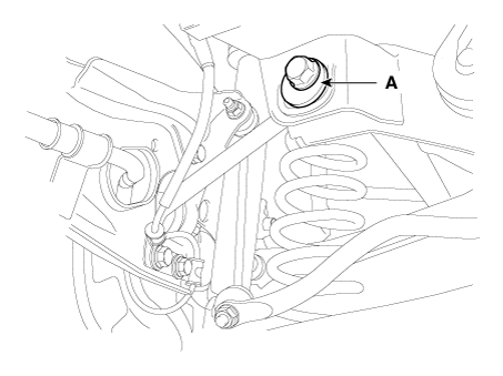
Loosen the nut holding the assist arm cam bolt (A). |
| 2. |
Adjust rear toe by turning the rear assist arm cam bolt (A) clockwise or counter clockwise. Toe adjustment should be made by turning the right and left cam bolt by the same amount.
|
| 3. |
When completing the toe adjustment, tighten the nut to specified torque.
|
Camber
Camber is pre-set at the factory, so it does not need to be adjusted. If the camber is not within the standard value, replace or repair the damaged parts and then inspect again.
|
Camber : -1.2° ± 0.5° |
 Wheel Repair procedures
Hub nut tightening sequence
Tighten the hub nuts in the following sequence.
Tightening torque:
88.3 - 107.9 N·m (9.0 - 11.0 kgf·m, 65.1 - 79.6 lb·ft)
...

Other information:
Kia Niro 2017 (DE HEV) Service Manual: Hybrid Power Control Unit (HPCU) Repair procedures
Removal
•
Be sure to read and follow the “General Safety Information and
Caution” before doing any work related with the high voltage system.
Failure to follow the safety instr ...
Kia Niro (DE HEV) Owners Manual: Emergency Stop Signal (ESS)
The Emergency Stop Signal system alerts the driver behind by blinking the stop
light when the vehicle is braked rapidly and severely.
The system is activated when:
The vehicle suddenly stops (vehicle speed is over 55km/h and the vehicle
deceleration at greater than 7 m/s2)
The ABS is act ...
