Kia Niro: Fuses And Relays / Relay Box (Engine Compartment) Repair procedures
| Inspection |
| 1. |
Disconnect the negative (-) battery terminal. |
| 2. |
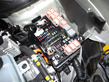
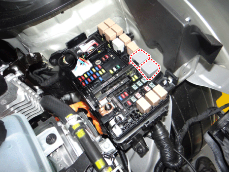
Pull out the relay from the engine compartment relay block. |
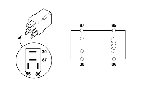
Power Relay (Type A)
Check for continuity between the terminals.
| 1. |
After supplying power to between No. 85 and 86 power relay terminals, check that there is continuity between No. 30 and 87 terminals. |
| 2. |
After disconnecting power between No. 85 and 86 power relay terminals, check that there is no continuity between No. 30 and 87 terminals. Engine Room Relay Block
|
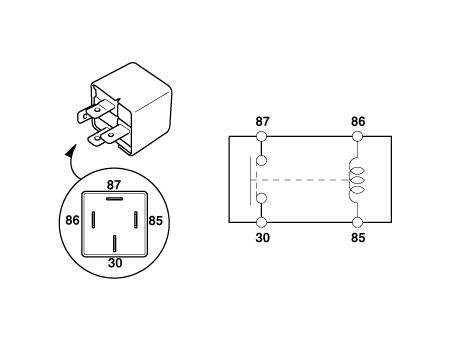
Power Relay (Type B)
Check for continuity between the terminals.
| 1. |
After supplying power to between No. 85 and 86 power relay terminals, check that there is continuity between No. 30 and 87 terminals. |
| 2. |
After disconnecting power between No. 85 and 86 power relay terminals, check that there is no continuity between No. 30 and 87 terminals.
|
Metal Core PCB block
| 1. |
Disconnect the negative (-) battery terminal. |
| 2. |
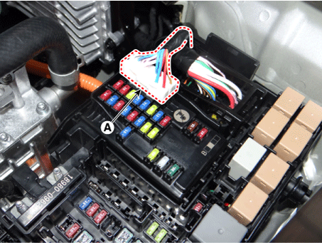
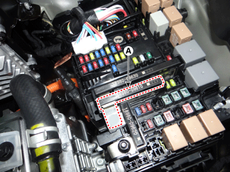
Disconnect the PCB block connector (A).
|
| 3. |
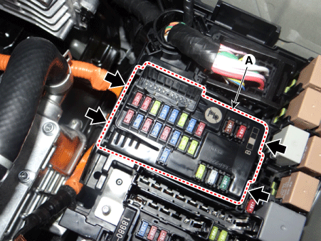
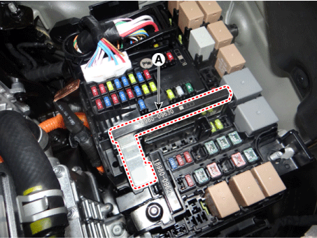
Push the four hooks in the direction of the arrow and lift up the metal core PCB block (A).
|
| 4. |
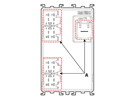
Remove the metal core PCB block by disconnecting the connectors (A).
|
Fuse
| 1. |
Check that the fuse holders are loosely held and that the fuses are securely fixed by the holders. |
| 2. |
Check that each fuse circuit has the exact fuse capacity. |
| 3. |
Check the fuses for any damage.
|
Multi Fuse
| (Multi Fuse A, B) |
| 1. |
Disconnect the negative (-) battery terminal. |
| 2. |
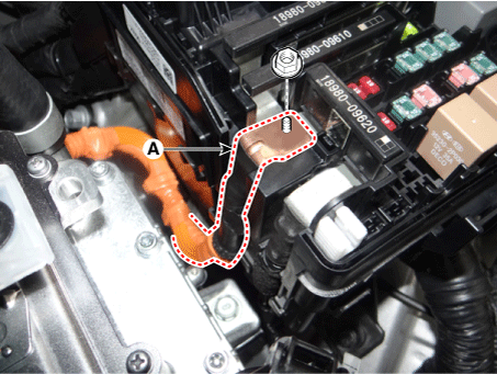
Remove the power cable terminal (A) after loosening the nut from the engine room fuse & relay box.
|
| 3. |
Remove the multi fuse A (A) after pushing the hook.
|
| 4. |
Remove the multi fuse B (A) after pushing the hook.
|
| (Multi Fuse C) |
| 1. |
Remove the multi fuse A and multi fuse B. |
| 2. |
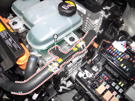
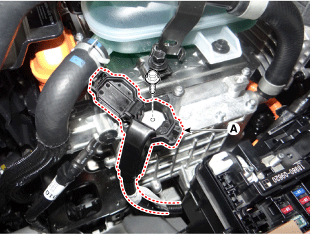
Remove the cooling & hose bracket (A) after loosening the mounting bolt.
|
| 3. |
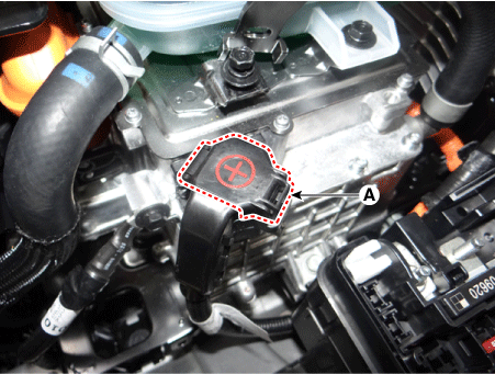
Remove the power cable terminal cap (A).
|
| 4. |
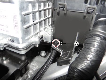
Remove the power cable terminal (A) after loosening the bolt from the HPCU.
|
| 5. |
Remove the engine room fuse & relay box power cable mounting clip (A).
|
| 6. |
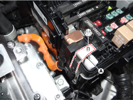
Remove the power cable terminal (A) after loosening the nut from the engine room fuse & relay box.
|
| 7. |
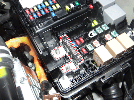
Remove the multi fuse C (A) after pushing the hook.
|
|
 Relay Box (Engine Compartment) Components and components location
Component Location
E/R Junction Block
Circuit (E/R Junction Block)
PCB Block
Circuit (PCB Block)
...
 Relay Box (Passenger Compartment) Components and components location
Component Location
IGPM
Circuit (IGPM)
ICM (Integrated Circuit Module) Relay
Box
...
Other information:
Kia Niro (DE HEV) Owners Manual: Engine compartment fuse panel (Battery terminal cover)
Engine room compartment fuse panel
Circuit (PCB Block)
Relay
...
Kia Niro (DE HEV) Owners Manual: Rocking the vehicle
If it is necessary to rock the vehicle to free it from snow, sand, or mud, first
turn the steering wheel right and left to clear the area around your front wheels.
Then, shift back and forth between R (Reverse) and any forward gear in vehicles
equipped with an Dual clutch transmission. Do not ...

