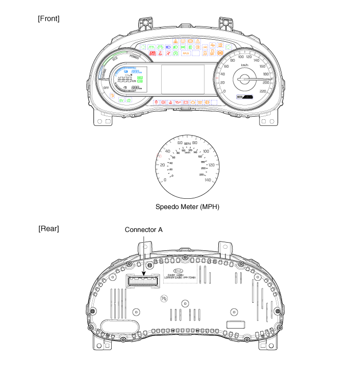
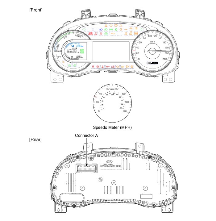
Kia Niro: Indicators And Gauges / Instrument Cluster Components and components location
Kia Niro 2017 (DE HEV) Service Manual / Body Electrical System / Indicators And Gauges / Instrument Cluster Components and components location
| Components |
| [Standard Type ("3.5")] |

| [Super Vision Type ("4.3")] |


Connector Pin Information
|
No. |
Description |
No. |
Description |
|
1 |
Ground |
21 |
Trip switch (-) |
|
2 |
Illumination (-) |
22 |
Trip switch 1 (+) |
|
3 |
Rheostat switch (Down)_Input |
23 |
Trip switch 2 (+) |
|
4 |
Rheostat switch (Up)_Input |
24 |
AT ('P' Position) |
|
5 |
- |
25 |
AT ('R' Position) |
|
6 |
Oil press switch_Input |
26 |
AT ('N' Position) |
|
7 |
Washer level low_Input |
27 |
AT ('D' Position) |
|
8 |
Alternator_Input |
28 |
AT ('S' Position) |
|
9 |
- |
29 |
Multimedia-CAN (Low) |
|
10 |
Driver mode switch_Input |
30 |
Multimedia-CAN (High) |
|
11 |
Dentent |
31 |
Active ECO switch_Input |
|
12 |
- |
32 |
Chassis-CAN (High) |
|
13 |
- |
33 |
Chassis-CAN (Low) |
|
14 |
Fuel sender (+)_Input |
34 |
Cluster speaker (+) |
|
15 |
- |
35 |
Cluster speaker (-) |
|
16 |
Fuel sender (-)_Input |
36 |
- |
|
17 |
Immobilizer_Input |
37 |
Ground |
|
18 |
Vehicle speed_Output |
38 |
IGN3 (PHEV Only) |
|
19 |
Air bag (+)_Input |
39 |
IGN 1 |
|
20 |
Tail lamp_Input |
40 |
Battery (+) |
 Troubleshooting
Troubleshooting
Error Item
Failure symptom
Inspection items
Detailed inspections
Relevant Parts/
Components
...
 Instrument Cluster Schematic diagrams
Circuit Diagram
[General Standard]
[General Supervision]
...
Other information:
Kia Niro 2017 (DE HEV) Service Manual: Instrument Cluster Repair procedures
Removal
•
Put on gloves to protect your hands.
•
When removing with a flat-tip screwdriver or remover, wrap protective
tape around the tools t ...
Kia Niro 2017 (DE HEV) Service Manual: Injector Troubleshooting
Signal Waveform
The three waveforms below are taken from the #1 and #4 injectors. The top waveform
is from the high side (feed side) of the #1 and #4 injectors, while the middle waveform
is from the low side (ground side) of the #1 injector and the bottom waveform is
from the low ...
© 2016-2024 www.kniro.net

