Kia Niro: Hybrid Control System / Hybrid Control Unit (HCU) Schematic diagrams
| HCU Terminal And Input/Output Signal |

| Terminal Function |
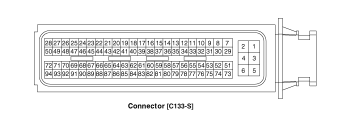
Connector [C133-S]
|
Pin No. |
Description |
Connected to |
|
1 |
HCU ground |
Chassis ground |
|
2 |
HCU ground |
Chassis ground |
|
3 |
HCU ground |
Chassis ground |
|
4 |
Battery power (B+) |
Battery |
|
5 |
Battery power (B+) |
Battery |
|
6 |
Battery power (B+) |
Battery |
|
7 |
- |
|
|
8 |
- |
|
|
9 |
- |
|
|
10 |
- |
|
|
11 |
- |
|
|
12 |
- |
|
|
13 |
- |
|
|
14 |
- |
|
|
15 |
Brake Switch 2 signal input |
Brake Switch (NC, IG1) |
|
16 |
Brake Switch 1 signal input |
Brake Switch (NO, B+) |
|
17 |
- |
|
|
18 |
- |
|
|
19 |
- |
|
|
20 |
- |
|
|
21 |
- |
|
|
22 |
- |
|
|
23 |
- |
|
|
24 |
- |
|
|
25 |
- |
|
|
26 |
- |
|
|
27 |
- |
|
|
28 |
- |
|
|
29 |
- |
|
|
30 |
- |
|
|
31 |
- |
|
|
32 |
- |
|
|
33 |
- |
|
|
34 |
- |
|
|
35 |
- |
|
|
36 |
- |
|
|
37 |
- |
|
|
38 |
Start signal input |
Inhibitor Switch |
|
39 |
- |
|
|
40 |
- |
|
|
41 |
- |
|
|
42 |
- |
|
|
43 |
- |
|
|
44 |
- |
|
|
45 |
- |
|
|
46 |
- |
|
|
47 |
- |
|
|
48 |
- |
|
|
49 |
- |
|
|
50 |
- |
|
|
51 |
- |
|
|
52 |
- |
|
|
53 |
- |
|
|
54 |
- |
|
|
55 |
- |
|
|
56 |
- |
|
|
57 |
- |
|
|
58 |
- |
|
|
59 |
- |
|
|
60 |
- |
|
|
61 |
- |
|
|
62 |
- |
|
|
63 |
- |
|
|
64 |
- |
|
|
65 |
- |
|
|
66 |
- |
|
|
67 |
- |
|
|
68 |
- |
|
|
69 |
- |
|
|
70 |
- |
|
|
71 |
- |
|
|
72 |
- |
|
|
73 |
IGN signal input |
Smart Key Unit |
|
74 |
- |
|
|
75 |
L - CAN [High] |
Engine clutch Actuator |
|
76 |
L - CAN [Low] |
Engine clutch Actuator |
|
77 |
- |
|
|
78 |
Powertrain CAN [High] |
Other control modules |
|
79 |
Powertrain CAN [Low] |
Other control modules |
|
80 |
- |
|
|
81 |
Hybrid CAN [High] |
Other control modules |
|
82 |
Hybrid CAN [Low] |
Other control modules |
|
83 |
- |
|
|
84 |
- |
|
|
85 |
- |
|
|
86 |
- |
|
|
87 |
- |
|
|
88 |
- |
|
|
89 |
- |
|
|
90 |
- |
|
|
91 |
- |
|
|
92 |
- |
|
|
93 |
- |
|
|
94 |
- |
|
| Input/Output signal |
Connector [C133-S]
|
Pin no. |
Description |
Condition |
Type |
Level |
|
1 |
HCU ground |
Always |
DC Voltage |
Max. 50mV |
|
2 |
HCU ground |
Always |
DC Voltage |
Max. 50mV |
|
3 |
HCU ground |
Always |
DC Voltage |
Max. 50mV |
|
4 |
Battery power (B+) |
Always |
DC Voltage |
Battery Voltage |
|
5 |
Battery power (B+) |
Always |
DC Voltage |
Battery Voltage |
|
6 |
Battery power (B+) |
Always |
DC Voltage |
Battery Voltage |
|
7 |
- |
|
|
|
|
8 |
- |
|
|
|
|
9 |
- |
|
|
|
|
10 |
- |
|
|
|
|
11 |
- |
|
|
|
|
12 |
- |
|
|
|
|
13 |
- |
|
|
|
|
14 |
- |
|
|
|
|
15 |
Brake Switch 2 signal input |
IG ON |
DC Voltage |
Battery Voltage |
|
16 |
Brake Switch 1 signal input |
Always |
DC Voltage |
Battery Voltage |
|
17 |
- |
|
|
|
|
18 |
- |
|
|
|
|
19 |
- |
|
|
|
|
20 |
- |
|
|
|
|
21 |
- |
|
|
|
|
22 |
- |
|
|
|
|
23 |
- |
|
|
|
|
24 |
- |
|
|
|
|
25 |
- |
|
|
|
|
26 |
- |
|
|
|
|
27 |
- |
|
|
|
|
28 |
- |
|
|
|
|
29 |
- |
|
|
|
|
30 |
- |
|
|
|
|
31 |
Sensor power (+5V) |
IG ON |
DC Voltage |
4.9 - 5.1V |
|
32 |
Sensor ground |
IG ON |
DC Voltage |
Max. 50mV |
|
33 |
Clutch Pressure Sensor (CPS) signal input |
IG ON |
Analog |
0.5 - 4.5V |
|
34 |
- |
|
|
|
|
35 |
- |
|
|
|
|
36 |
- |
|
|
|
|
37 |
- |
|
|
|
|
38 |
Start signal input |
IG ST |
DC Voltage |
Battery Voltage |
|
39 |
- |
|
|
|
|
40 |
- |
|
|
|
|
41 |
- |
|
|
|
|
42 |
- |
|
|
|
|
43 |
- |
|
|
|
|
44 |
- |
|
|
|
|
45 |
- |
|
|
|
|
46 |
- |
|
|
|
|
47 |
- |
|
|
|
|
48 |
- |
|
|
|
|
49 |
- |
|
|
|
|
50 |
- |
|
|
|
|
51 |
- |
|
|
|
|
52 |
- |
|
|
|
|
53 |
- |
|
|
|
|
54 |
- |
|
|
|
|
55 |
- |
|
|
|
|
56 |
- |
|
|
|
|
57 |
- |
|
|
|
|
58 |
- |
|
|
|
|
59 |
- |
|
|
|
|
60 |
- |
|
|
|
|
61 |
- |
|
|
|
|
62 |
- |
|
|
|
|
63 |
- |
|
|
|
|
64 |
- |
|
|
|
|
65 |
- |
|
|
|
|
66 |
- |
|
|
|
|
67 |
- |
|
|
|
|
68 |
- |
|
|
|
|
69 |
- |
|
|
|
|
70 |
- |
|
|
|
|
71 |
- |
|
|
|
|
72 |
- |
|
|
|
|
73 |
IGN signal input |
IG ON |
DC Voltage |
Battery Voltage |
|
74 |
- |
|
|
|
|
75 |
L - CAN [High] |
IG ON |
Pulse |
|
|
76 |
L - CAN [Low] |
IG ON |
Pulse |
|
|
77 |
- |
|
|
|
|
78 |
Powertrain CAN [High] |
IG ON |
Pulse |
Dominant:2.75 - 4.5(3.5)V Receive:2.0 - 3.0(2.5)V |
|
79 |
Powertrain CAN [Low] |
IG ON |
Pulse |
Receive:2.0 - 3.0(2.5)V Dominant:0.5 - 2.25(1.5)V |
|
80 |
- |
|
|
|
|
81 |
Hybrid CAN [High] |
IG ON |
Pulse |
Dominant:2.75 - 4.5(3.5)V Receive:2.0 - 3.0(2.5)V |
|
82 |
Hybrid CAN [Low] |
IG ON |
Pulse |
Receive:2.0 - 3.0(2.5)V Dominant:0.5 - 2.25(1.5)V |
|
83 |
- |
|
|
|
|
84 |
- |
|
|
|
|
85 |
- |
|
|
|
|
86 |
- |
|
|
|
|
87 |
- |
|
|
|
|
88 |
- |
|
|
|
|
89 |
- |
|
|
|
|
90 |
- |
|
|
|
|
91 |
- |
|
|
|
|
92 |
- |
|
|
|
|
93 |
- |
|
|
|
|
94 |
- |
|
|
|
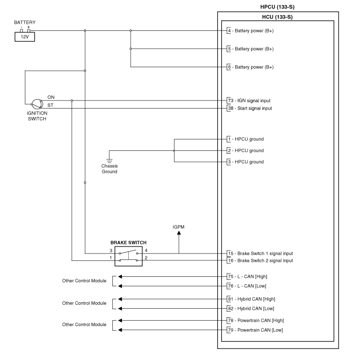
| Circuit Diagram |

 Hybrid Power Control Unit (HPCU) Repair procedures
Removal
•
Be sure to read and follow the “General Safety Information and
Caution” ...
 Hybrid Control Unit (HCU) Repair procedures
Removal
•
Be sure to read and follow the “General Safety Information and
Caution” ...
Other information:
Kia Niro (DE HEV) Owners Manual: Electronic power steering
Power steering uses the motor to assist you in steering the vehicle. If the engine
is off or if the power steering system becomes inoperative, the vehicle may still
be steered, but it will require increased steering effort.
Electronic power steering is controlled by the power steering control u ...
Kia Niro (DE HEV) Owners Manual: If you have a flat tire (with tire mobility kit)
■ 18 inch tire
■ 16 inch tire
Please read the instructions before using the Tire Mobility Kit.
(1) Compressor
(2) Sealant bottle
The Tire Mobility Kit is a temporary fix to the tire and we recommend that the
tire inspected by an authorized Kia dealer as soon as possible.
CAUTION - On ...
