Kia Niro: Lane Departure Warning System (LDWS) / Description and operation
| Description |
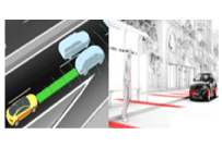
System block diagram
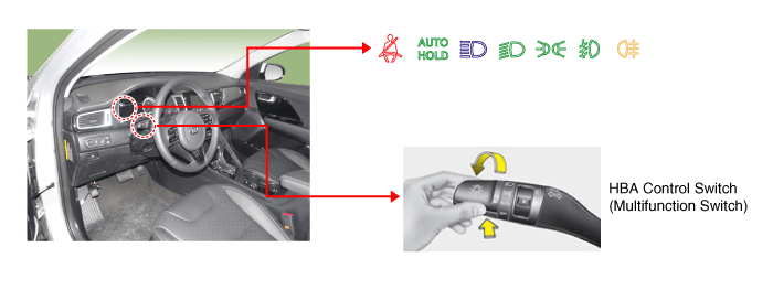
Components of LDWS
|
No |
Item |
Function |
Position |
||||||
|
1 |
LDWS Unit |
|
Windshield Glass |
||||||
|
2 |
LDWS Switch |
LDWS On/Off Switch |
Crash Pad (Left) |
||||||
|
3 |
Multifunction Switch |
HBA On/Off Switch (MF : Auto mode) |
Steering Wheel |
||||||
|
4 |
User Setting Menu |
SLIF On/Off, Menu |
Cluster menu |
||||||
|
5 |
Cluster/Buzzer |
SLIF/LDWS Warning |
Cluster |
Camera unit of the LDWS processes the following functions using the video signal input.
| – |
Detects and analyzes the current driving lane |
| – |
Detects the light from foregoing vehicle and oncoming vehicle |
| – |
Detects and analyzes the status of foregoing vehicle and oncoming vehicle, and sets off warning sound (or message) for driver if necessary. |
| – |
Transmits the information via high speed CAN communication |
| 1. |
Lane Departure Warning System (LDWS) unit
The lane departure warning system is a convenient feature that detects the lanes ahead by using the camera image and vehicle signal data to alarm the driver in case the vehicle deviates from the lane. It consists of the camera unit used to detect the lane by analyzing the camera image input signal. The sensor module that processes screen image by sensing the lanes ahead on the camera unit, senses the lanes and analyzes the key parameters, i.e. vehicle center offset, road width, vehicle driving angle and road curvature, to keep to the lane. The following procedure is the lane detecting process through screen image processing.
|
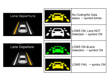
| 2. |
LDWS Operation process When the LDWS switch is pressed, the operation state of the lane departure warning system is displayed at the center of the cluster as long as the LDWS lamp is turned on. The specific classification of the displays is shown in the following table.
|
||||||||||||||||||||
| 3. |
High Beam Assist
|
||||||||||||||||||||

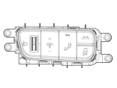
LDWS ON/OFF switch (A)
When the LDWS switch is pressed, the LDWS is activated as long as the LDWS lamp is turned on. When the switch is pressed again, the LDWS is turned off and the display lamp is turned off.
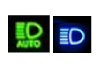
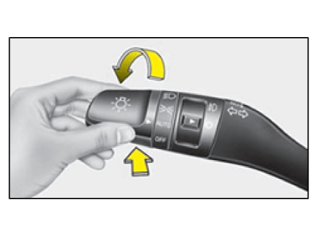
High Beam Auto Control Switch: High Beam Auto Control System is turned ON if the Multifunction Switch Light SW is set to AUTO, and the Light SW is set to High Beam position (Pushed).
| – |
If the Light SW is not set to AUTO, or to High Beam position, the High Beam Auto Control System is turned OFF. |
Alarm of LDWS
| 1. |
Visual alarm : The lane toward the direction of departure blinks in "amber". |
Operating conditions of LDWS
The operating conditions of LDWS are as below.
| 1. |
The LDWS switch is turned "ON". The LDWS lamp on the instrument panel is turned on when the switch is on. |
| 2. |
LDWS function is set and the vehicle speed exceeds 60 km/h (37 mph). The alarm stops momentarily when the vehicle speed falls below 60 - 55 km/h (37 - 34 mph) and restarts if the vehicle speed is over 60 km/h (37 mph). |
| 3. |
If the driver operates the left or right turn signal lamps to show the intention of lane change, the alarm will be deactivated regardless of the direction of lane departure. The lane departure alarm function restarts 2 seconds after switching off the left or right turn signal lamps. The alarm is deactivated while operating the hazard lamps. |
| 4. |
Switch on the turn signal lamp before changing the lanes. Arbitrary change of lanes without operating the turn signal to the driving direction will generate alarm. |
| 5. |
When more than 40% of the vehicle body has crossed the lane, the alarm is released by sensing departure for lane change. |
| 6. |
The lane departure alarming is not made when the vehicle drives at the center of the lane.
|


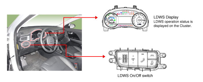
 Components and components location
Components
1. LDWS ON/OFF switch
2. Instrument cluster
3. LDWS unit (MFC)
? MFC : Multi Function Camera
–
Function : LDWS, ...
 Repair procedures
Service Point Target Auto
Calibration (SPTAC)
This procedure provides a way to calibrate the camera by having the service technician
align the car to a well lit simulated straight r ...
Other information:
Kia Niro 2017 (DE HEV) Service Manual: CVVT Oil Control Valve (OCV) Repair procedures
Inspection
1.
Switch "OFF" the ignition.
2.
Disconnect the OCV connector.
3.
Measure resistance between the OCV terminals 1 and 2.
4.
Check that the resistance is within the specificat ...
Kia Niro 2017 (DE HEV) Service Manual: Steering Gear box Repair procedures
Removal
1.
Disconnect the battery negative cable.
2.
Remove the universal bolt (A).
Tightening torque :
32.4 - 37.3 N·m (3.3 - 3.8 kgf·m, 23.9 - 27.5 lb·ft)
...
