Kia Niro: AHB(Active Hydraulic Boost) System / Brake Actuation Unit Repair procedures
| Removal |
| 1. |
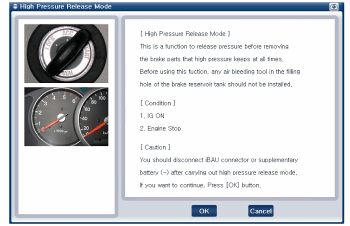
Turn ignition switch OFF and disconnect the negative (-) battery terminal. |
| 2. |
Disconnect the TCM connector. (Refer to DCT (Dual Clutch Transmission) System - "DCT Control Module (TCM)) |
| 3. |
Disconnect the ECM connector. |
| 4. |
Remove the air cleaner assembly. (Refer to Engine Mechanical System - "Air Cleaner") |
| 5. |
Remove the brake fluid from the reservoir .
|
| 6. |
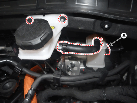
Remove the nuts, hose, brake fluid level sensor connector (A).
|
| 7. |
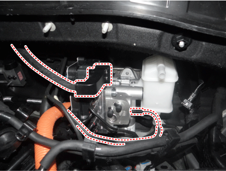
Disconnect the integrated brake actuation unit (IBAU) connector and brake tube.
|
| 8. |
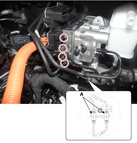
Loosen the flare nuts (A) from the integrated brake actuation unit (IBAU) and then remove the brake tube.
|
| 9. |
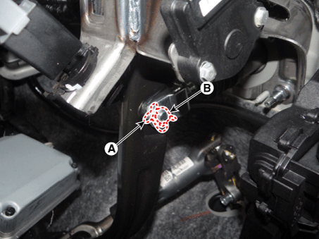
Remove the snap pin (A) and clebis pin (B).
|
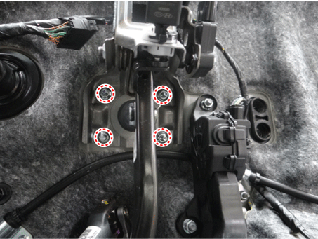
| 10. |
Loosen the brake pedal nuts.
|
| Installation |
| 1. |
Installation is the reverse of removal. |
| 2. |
Check the brake pedal operation. |
| 3. |
After filling the brake fluid in the reservoir, perform the air bleed. (Refer to the Brake system - "Brake Bleeding Procedure") |
| 4. |
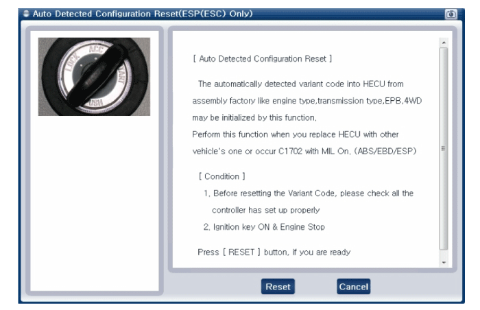
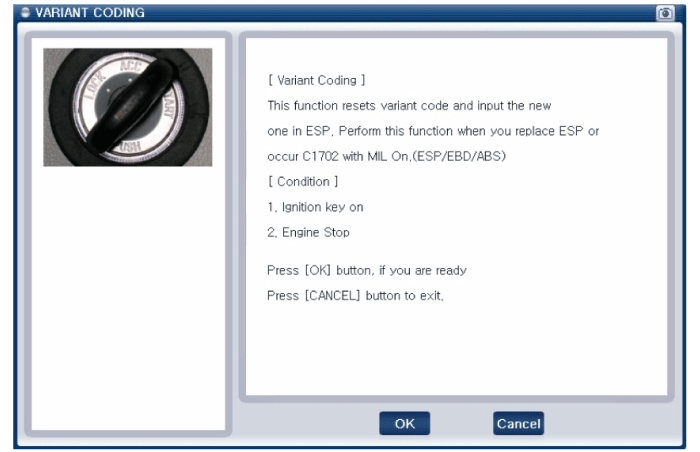
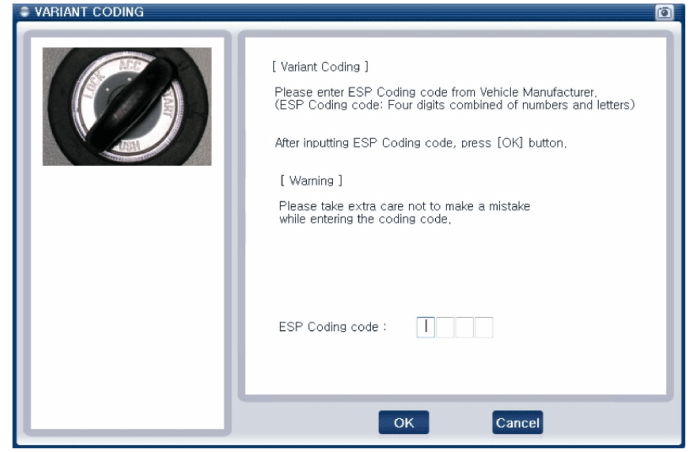
Conduct the variant coding. |
| 5. |
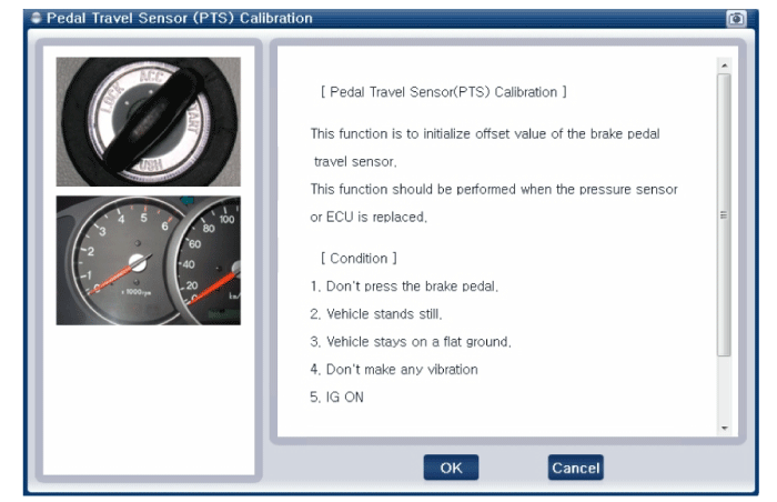
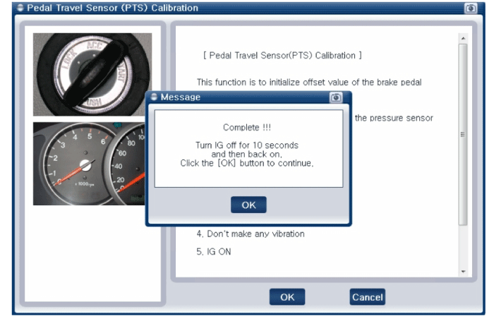
Conduct the pedal traval sensor (PTS) calibration. |
| 6. |
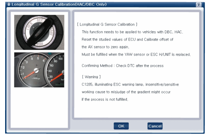
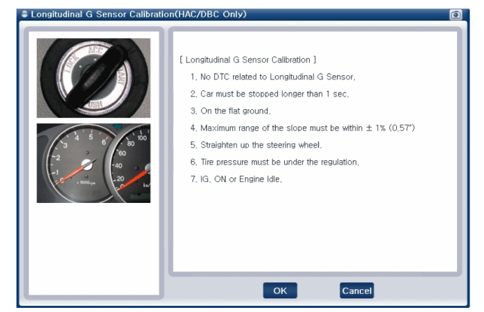
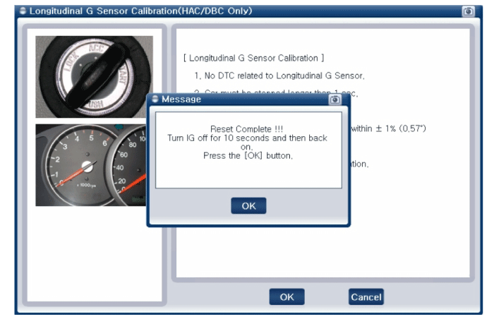
Conduct the longitidinal G sensor clibration. (HAC/DBC Only) |
| 7. |
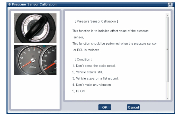
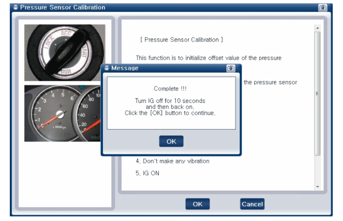
Conduct the pressure sensor calibration. |
| 8. |
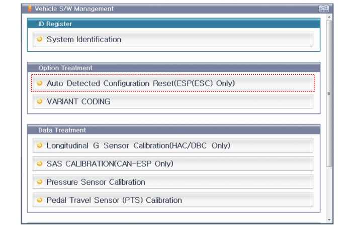
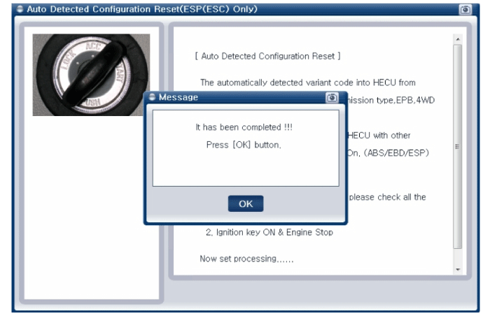
Conduct the auto detected configuration reset the if necessary. |
| Diagnosis by using diagnostic device |
The following section describes how to diagnose faults using a diagnostic instrument.
| 1. |
Connect the diagnostic instrument to the self-diagnostic connector (16-pin) beneath the crash pad on the side of driver's seat, and then turn on the ignition to activate the diagnostic instrument. |
| 2. |
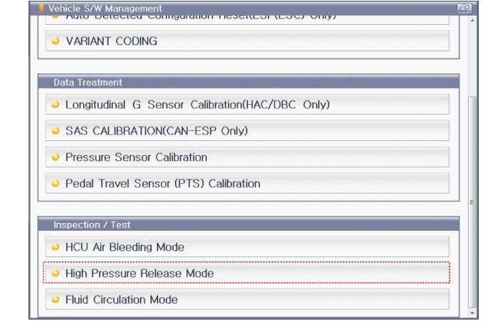
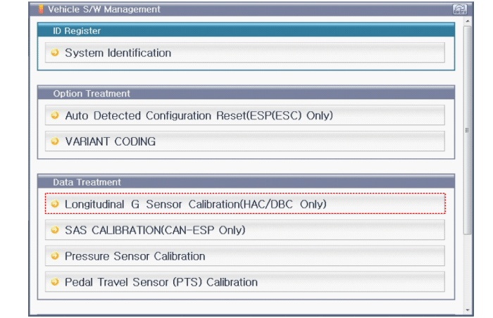
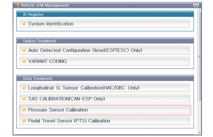
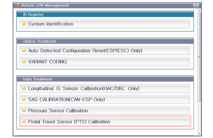
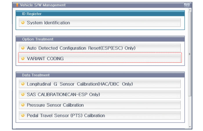
In the GDS vehicle type selection menu, select "Vehicle Type" and "Brake/VDC/AHB" System. Longitudinal G Sensor Calibration(HAC/DBC Only)
Pressure Sensor Calibration
Pedal Travel Sensor (PTS) Calibration
Auto Detected Configuration Reset(ESP(ESC) Only)
VARIANT CODIN
|
 Brake Actuation Unit Components and components location
Components
1. Integrated Brake Actuation Unit (IBAU) ECU
2. Reservoir
3. Pedal simulator
4. Integrated Brake Actuation Unit (IBAU)
...
 Pressure Source Unit Components and components location
Components
1. Pressure Source Unit (PSU)
2. Motor
3. Filler adapter
4. Accumulator
5. Bracket
...
Other information:
Kia Niro 2017 (DE HEV) Service Manual: Components and components location
Components (1)
[General Type]
1. Sun visor [LH]
2. Sun visor [RH]
3. Roof trim
4. Assist handle bracket
Components (2)
[Sunroof Type]
1. Sun visor [LH]
2. Sun visor [RH]
...
Kia Niro 2017 (DE HEV) Service Manual: Gear Actuator Assembly Components and components location
Component Location
1. Gear actuator assembly
2. Shift motor 2 (Even)
3. Shift motor 1 (Odd)
4. Select solenoid 2 (Even)
5. Select solenoid 1 (Odd)
...


